Editing layers#
NextGIS Mobile allows you to edit vector layers added to the map. While editing, you can:
add new features;
delete features;
edit features.
Switching to Edit mode#
There are several ways to switch to Edit mode.
The first way is Main actions button (the big blue button in the right bottom corner of map screen). Pressing Main actions button opens a menu of most common actions (see Fig. 945.).
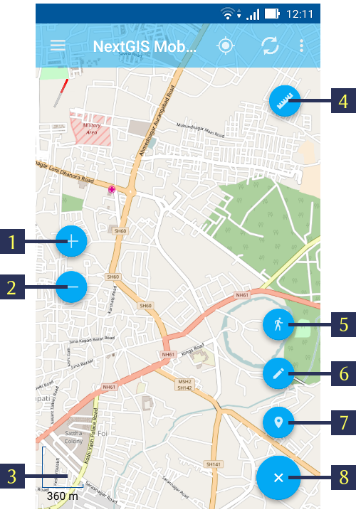
Fig. 945. Common actions menu#
The numbers indicate: 1 - Zoom in; 2 - Zoom out; 3 – Scale ruler; 4 - Measure button; 5 - Add geometry by walk; 6 - Edit layers; 7 - Add current location; 8 - Close Common actions menu.
You need to tap the pencil button (item 6 in Fig. 945.) to switch to Edit mode.
Then select a vector layer you want to edit in an opened dialog (see Fig. 946.).
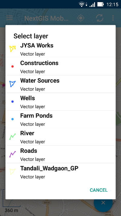
Fig. 946. Select layer dialog#
The second way to switch to Edit mode is to long-press the feature on the Map. This will activate Edit mode for the layer which includes this feature. (A short press will activate a similar menu, but only the “info” icon will be available.) If there are multiple overlaying features, a list will appear. Select the layer you wish to edit from that list.
The third way is to open Layers tree panel (item 1 in Fig. 903.) and tap on Layer contextual menu icon next to the vector layer name . This will open the contextual menu items. There you need to select “Edit”.
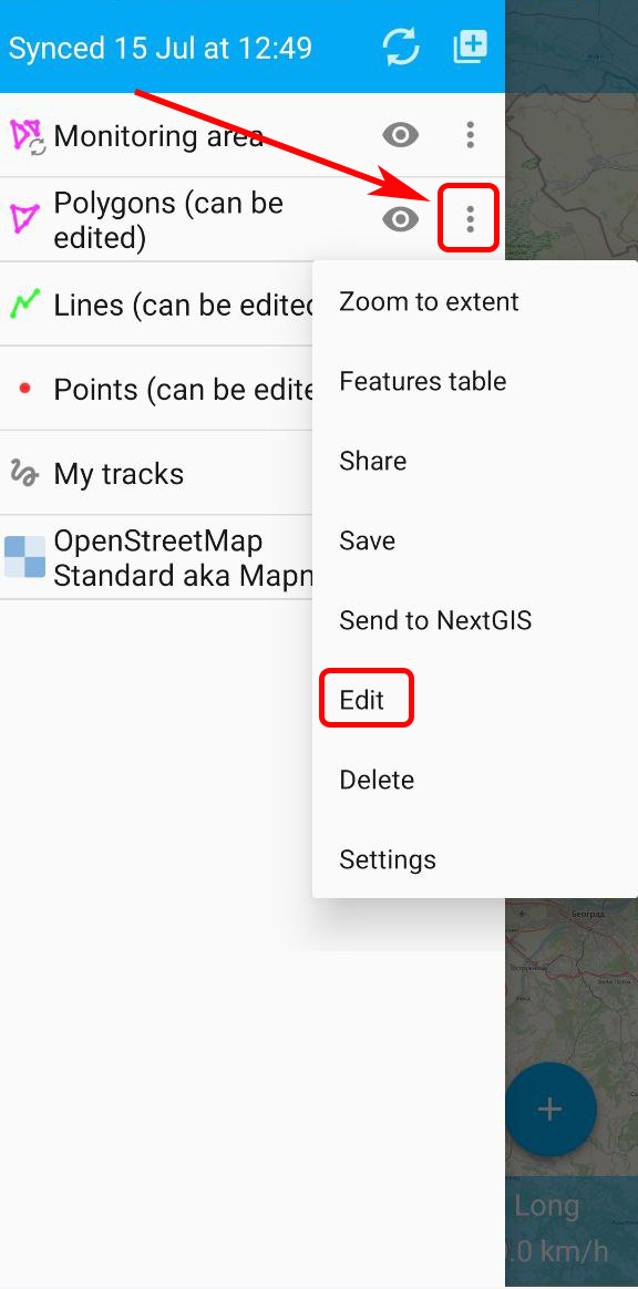
Fig. 947. Layer context menu#
The Editing Toolbar#
After switching to Edit mode using any of the methods described in Switching to Edit mode section Editing Toolbar is opened at the bottom of the map screen (see Fig. 948.).
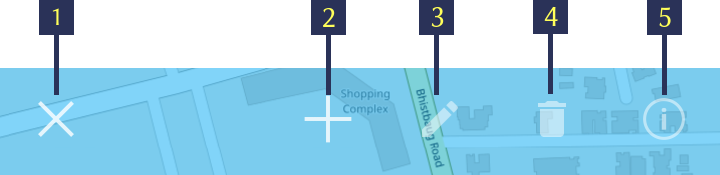
Fig. 948. Editing Toolbar.#
The numbers indicate: 1 - Quit Edit mode; 2 - Add new feature; 3 – Edit feature; 4 - Delete feature; 5 - Attributes info.
Note
This editing toolbar is common for all vector layers irrespective of the type of geometry they contain (point, line or polygon).
Adding features#
To create a new feature first select a layer you want to add this feature to. Then switch to Edit mode using any of the methods described in Switching to Edit mode section.
After Editing Toolbar is opened tap “Add new feature” button (item 2 in Fig. 948.).
Note
Type of geometry of a new feature should correspond to the type of geometry of the layer you want to add this feature to (e.g. you can only add a new point to a point/multipoint vector layer, a new line - to a line/multiline vector layer, etc.).
Note
If you want to start adding new features from scratch first you have to create an empty layer as described in Creating new vector layer section.
Adding a point#
To create a new point first select a point/multipoint vector layer you want to add this feature to. Then switch to Edit mode using any of the methods described in Switching to Edit mode section.
Tap “Add new feature” button in Editing Toolbar (item 2 in Fig. 948.).
In a point layer a new point will appear in the center of the screen highlighted in red. You can move this point anywhere on the map simply by dragging the circular handle attached to it. The red crosshair marker indicates the center of Map screen (see Fig. 949.).
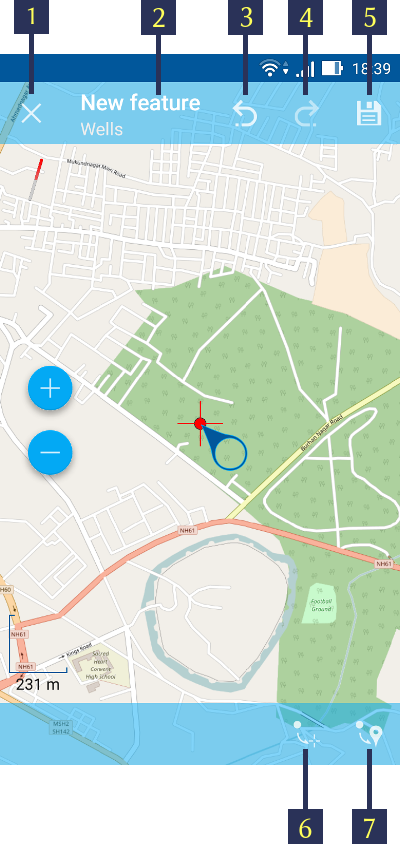
Fig. 949. Adding a point to Point layer.#
The numbers indicate: 1 - Quit (without saving); 2 - Feature ID & Name of the Layer; 3 - Undo changes; 4 - Redo changes; 5 - Set attributes; 6 - Move point to the center of Map screen; 7 - Move point to the current location.
For adding a point to a multipoint layer execute steps 1-2 and then tap “Add point” (item 6 in Fig. 950.). After that you can set point’s location as described above in the step 3.
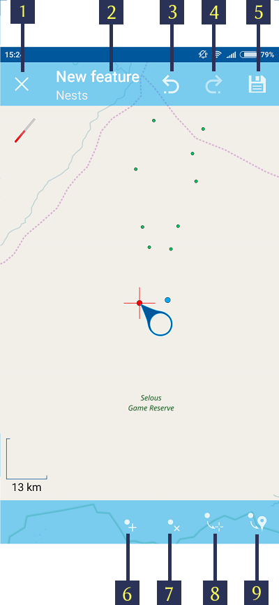
Fig. 950. Adding a point to Multipoint layer.#
The numbers indicate: 1 - Quit (without saving); 2 - Feature ID & Name of the Layer; 3 - Undo changes; 4 - Redo changes; 5 - Set attributes; 6 - Add point; 7 - Delete point; 8 - Move point to the center of Map screen; 9 - Move point to the current location.
After a geometry of new point is added you may set its attributes by tapping on the “floppy” button (item 5 in Fig. 949. and Fig. 950.). Pressing floppy icon will save a new point and open Attributes editing form (see Fig. 951.).
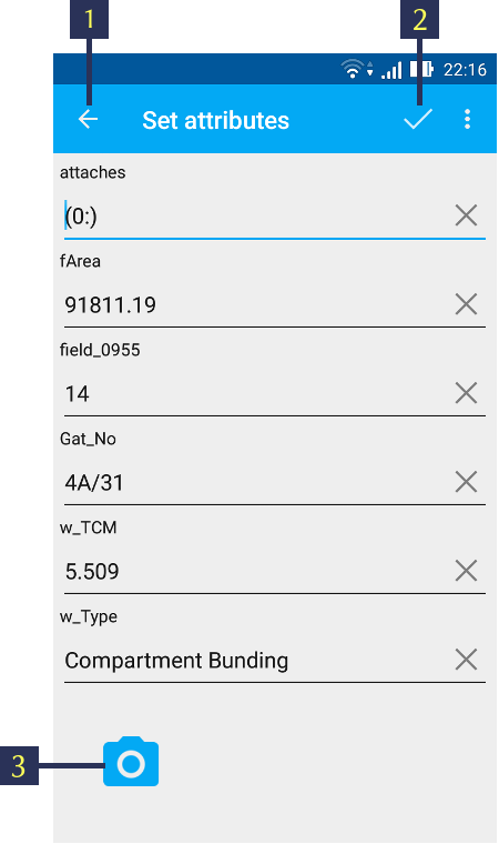
Fig. 951. Attributes editing form.#
The numbers indicate: 1 - Back to previous screen; 2 - Apply changes; 3 - Add photo.
When all the attributes are set tap “Apply changes” button (item 2 in Fig. 951.) to save the attributes. If you tap “Back” button instead (item 1 in Fig. 951.) the app will warn you of any unsaved changes. You can also attach photos to each feature using “Add photo” button in Attributes editing form (item 3 in Fig. 951.).
See how to add and label points in our videos:
Watch on youtube.
Watch on youtube.
Adding a line#
To create a new line first select a linestring/multilinestring vector layer you want to add this feature to. Then switch to Edit mode using any of the methods described in Switching to Edit mode section.
Tap “Add new feature” button in Editing Toolbar (item 2 in Fig. 948.).
In a linestring layer a new line will appear in the center of the screen, with one of its vertices highlighted in red (see Fig. 952.).
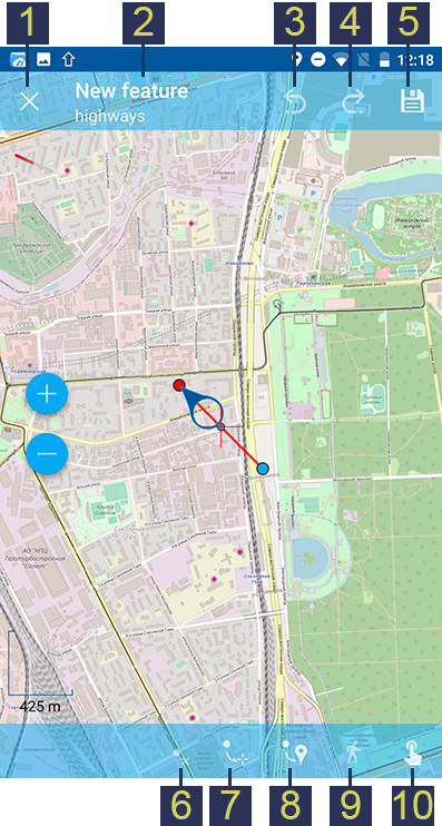
Fig. 952. Adding a line to Linestring layer.#
The numbers indicate: 1 - Quit (without saving); 2 - Feature ID & name of the Layer; 3 - Undo changes; 4 - Redo changes; 5 - Set attributes; 6 - Delete vertex; 7 - Move vertex to the center of Map screen; 8 - Move vertex to the current location; 9 - Append geometry by walk; 10 - Edit by touch.
You can move the vertices anywhere on the map simply by dragging the circular handle attached to the selected vertex. If you tap on the vertex in the middle of the line, two new vertices will be created automatically. This way you can add as many vertices as you need and shape the line geometry any way you like, including smooth curves.
For adding a line to a multilinestring layer execute steps 1-2 and then tap “Add line” (item 6 in Fig. 953.). After that you can set vertices’ location as described above in the step 3.

Fig. 953. Adding a line to Multilinestring layer.#
The numbers indicate: 1 - Quit (without saving); 2 - Feature ID & name of the Layer; 3 - Undo changes; 4 - Redo changes; 5 - Set attributes; 6 - Add line; 7 - Delete line; 8 - Delete vertex; 9 - Move vertex to the center of Map screen; 10 - Move vertex to the current location; 11 - Contextual menu with the rest of commands (Append geometry by walk, Append geometry by touch).
After a geometry of new line is added you may set its attributes by tapping on the “floppy” button (item 5 in Fig. 952. and Fig. 953.). Pressing floppy icon will save a new line and open Attributes editing form (see Fig. 951.).
When all the attributes are set tap “Apply changes” button (item 2 in Fig. 951.) to save the attributes. If you tap “Back” button instead (item 1 in Fig. 951.) the app will warn you of any unsaved changes. You can also attach photos to each feature using “Add photo” button in Attributes editing form (item 3 in Fig. 951.).
Adding a polygon#
To create a new polygon first select a polygon/multipolygon vector layer you want to add this feature to. Then switch to Edit mode using any of the methods described in Switching to Edit mode section.
Tap “Add new feature” button in Editing Toolbar (item 2 in Fig. 948.).
In a polygon layer a new polygon will appear in the center of the screen, with one of its vertices highlighted in red (see Fig. 954.).
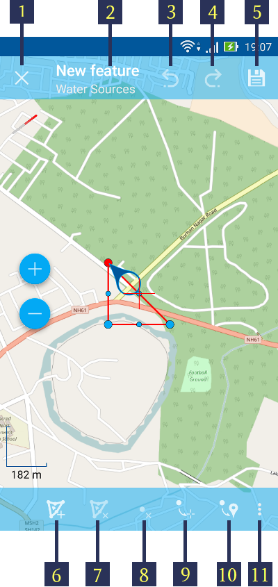
Fig. 954. Adding a polygon to Polygon layer.#
The numbers indicate: 1 - Quit (without saving); 2 - Feature ID & name of the Layer; 3 - Undo changes; 4 - Redo changes; 5 - Set attributes; 6 - Add hole; 7 - Delete hole; 8 - Delete vertex; 9 - Move vertex to the center of Map screen, 10 - Move vertex to the current location, 11 - Contextual menu with the rest of commands (Append geometry by walk, Append geometry by touch).
You can move the vertices anywhere on the map simply by dragging the circular handle attached to the selected vertex. If you tap on the vertex in the middle of the line, two new vertices will be created automatically. This way you can add as many vertices as you need and shape the polygon geometry any way you like, including smooth curves.
You can also create holes in polygons by tapping button “Add hole” (item 6 in Fig. 954. or item 8 in Fig. 955.) and creating a hole geometry the same way you create polygon geometry.
Note
Hole geometry must be located INSIDE a polygon geometry otherwise the changes won’t be saved!
For adding a polygon to a multilipolygon layer execute steps 1-2 and then tap “Add polygon” (item 6 in Fig. 955.). After that you can set vertices’ location as described above in the step 3.
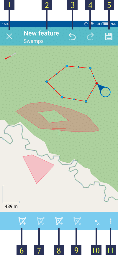
Fig. 955. Adding a polygon to Multipolygon layer.#
The numbers indicate: 1 - Quit (without saving); 2 - Feature ID & name of the Layer; 3 - Undo changes; 4 - Redo changes; 5 - Set attributes; 6 - Add polygon; 7 - Delete polygon; 8 - Add hole; 9 - Delete hole; 10 - Delete vertex; 11 - Contextual menu with the rest of commands (Move vertex to the center of Map screen, Move vertex to the current location, Append geometry by walk, Append geometry by touch).
After a geometry of new polygon is added you may set its attributes by tapping on the “floppy” button (item 5 in Fig. 954. and Fig. 955.). Pressing floppy icon will save a new line and open Attributes editing form (see Fig. 951.).
When all the attributes are set tap “Apply changes” button (item 2 in Fig. 951.) to save the attributes. If you tap “Back” button instead (item 1 in Fig. 951.) the app will warn you of any unsaved changes. You can also attach photos to each feature using “Add photo” button in Attributes editing form (item 3 in Fig. 951.).
Adding current location#
To add current location to a vector layer press Main actions button (item 8 in Fig. 903.), and then press a pushpin icon (item 7 in Fig. 945.). In an opened dialog select a layer you’d like to add current location to (only point/multipoint geometry will be displayed) (see Fig. 956.). If there is only one point/multipoint layer available, it will be selected automatically.
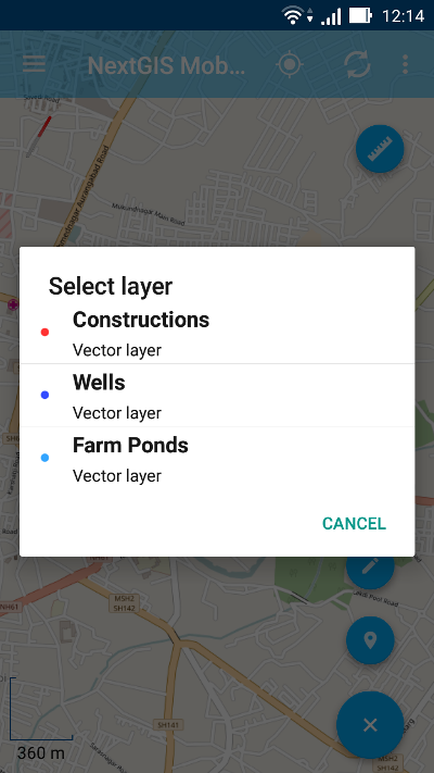
Fig. 956. Select layer dialog.#
Current location will be added to selected layer as a new point or a new multipoint consisting of 1 point.
You can then add attributes as described in Adding a point section.
Note
You can add current location to Point and Multipoint layers only!
Adding line or polygon by walk#
To add line or polygon by walk to a vector layer press Main actions button, and then press a walking man icon (item 5 in Fig. 945.). In an opened dialog select a layer you’d like to add a new feature to (only linestring/multilinestring and polygon/multipolygon layers will be displayed) (see Fig. 957.).
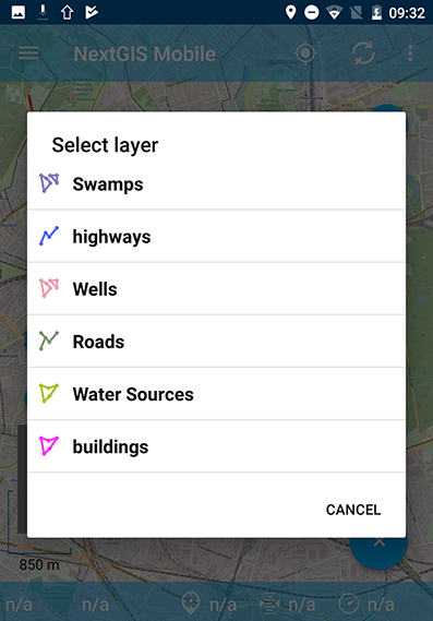
Fig. 957. Select layer dialog.#
Find more information about adding geometries in Record tracks to vector layer section.
Note
You can add tracks to either Linestring/Multilinestring or Polygon/Multipolygon layers!
Editing a geometry#
To edit an existing layer first select that vector layer and switch to Edit mode using any of the 3 methods described in Switching to Edit mode section. The feature will turn its colour to Blue. Then tap on the pencil icon in Bottom toolbar (item 3 in Fig. 948.). The feature will turn its colour to Red in edit mode.
Editing a point#
To start editing a point first select the point/multipoint layer in the Layer tree and switch to Edit mode, then select a point by pressing on it. It will change its colour to blue. Then tap on the pencil icon in Bottom toolbar (item 3 in Fig. 948.). The selected point feature will be highlighted in red and have an arrow pointing at it.
To change location of a selected point simply pull it or arrow pointing at it to a desired place. Also a point can be moved using buttons from Bottom toolbar - to the center of the screen shown as Red Crosshair marker (item 6 in Fig. 958.) or to the current device location (see item 7 in Fig. 958.).
You can cancel editing at any point of time, without saving changes, by close editing button. (see item 1 in Fig. 958.). The system will warn you about this.
In the end you can have your geofeatures digitized as shown below. See Fig. 958..
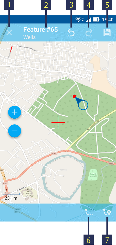
Fig. 958. Editing point.#
The numbers indicate: 1 - Close editing (without saving); 2 - Feature ID & name of the Layer; 3 - Undo changes; 4 - Redo changes; 5 - Set attributes; 6 - Move point to the Red Crossover (Center); 7 - Move point to the current location.
When you edit a multipoint all points included in it change their colour to blue. The selected point will be highlighted in red and have an arrow pointing at it (see Fig. 958.).
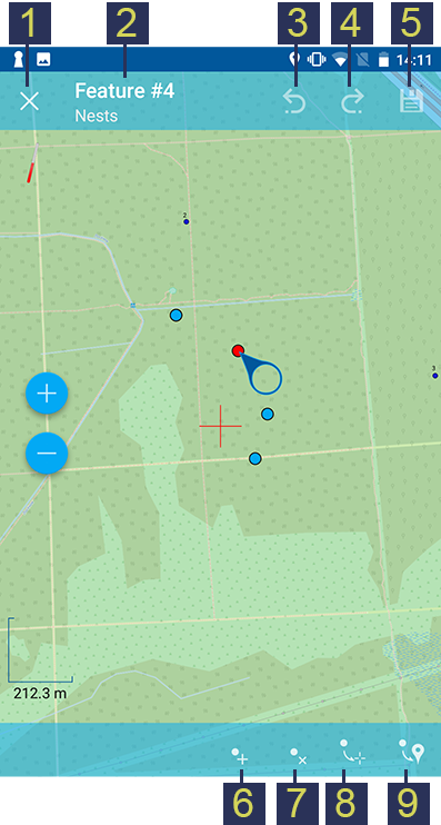
Fig. 959. Editing multipoint.#
The numbers indicate: 1 - Quit (without saving); 2 - Feature ID & Name of the Layer; 3 - Undo changes; 4 - Redo changes; 5 - Set attributes; 6 - Add point; 7 - Delete point; 8 - Move point to the center of Map screen; 9 - Move point to the current location.
You can delete selected point (item 7 in Fig. 959.), move it to a new location simply pulling it or arrow pointing at it to a desired place, to the center of the screen shown as Red Crosshair marker (item 8 in Fig. 959.) or to the current device location (item 9 in Fig. 959.). Also you can add a new point to the multipoint (item 6 in Fig. 959.).
Editing a line#
To start editing a line first select the linestring/multilinestring layer in the Layer tree and switch to Edit mode, then select a line by pressing on it. It will change its colour to blue. Then tap on the pencil icon in Bottom toolbar (item 3 in Fig. 948.). The line will change its colour to red and will show all its vertices. Current vertex is highlighted in red and has an arrow pointing at it. The center of line segment between vertices is also indicated. Pressing the center of line segment leads to two new vertex being added to the line.
Selected vertex can be moved simply by pulling it or arrow pointing at it to a desired place. Also a vertex can be moved using buttons from Bottom toolbar - to the center of the screen shown as Red Crosshair marker (item 7 in Fig. 960.) or to the current device location (see item 8 in Fig. 960.).
You can delete the unrequired vertex by highlighting it and tapping delete vertex (see item 6 in Fig. 960.)
In this way you can even get a smooth curve as per the geographic shape.
In the end you can have your geofeatures digitized as shown below. See Fig. 960..
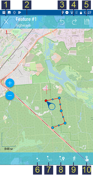
Fig. 960. Editing line.#
The numbers indicate: 1 - Quit (without saving); 2 - Feature ID & name of the Layer; 3 - Undo changes; 4 - Redo changes; 5 - Set attributes; 6 - Delete vertex; 7 - Move vertex to the center of Map screen; 8 - Move vertex to the current location; 9 - Append geometry by walk; 10 - Edit by touch.
Note
If only one vertex remains in a line this line is deleted automatically.
When you edit a multiline all points included in it change their colour to blue. The selected point will be highlighted in red and have an arrow pointing at it (see Fig. 961.)
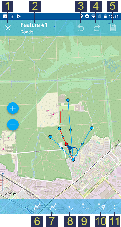
Fig. 961. Editing multiline.#
The numbers indicate: 1 - Quit (without saving); 2 - Feature ID & name of the Layer; 3 - Undo changes; 4 - Redo changes; 5 - Set attributes; 6 - Add line; 7 - Delete line; 8 - Delete vertex; 9 - Move vertex to the center of Map screen; 10 - Move vertex to the current location; 11 - Contextual menu with the rest of commands (Append geometry by walk, Append geometry by touch).
You can delete selected point or line (item 7 and 8 in Fig. 961.), move a point to a new location simply pulling it or arrow pointing at it to a desired place, to the center of the screen shown as Red Crosshair marker (item 9 in Fig. 961.) or to the current device location (item 10 in Fig. 961.). Also you can add a new line to the multiline (item 6 in Fig. 961.).
Editing a polygon#
To start editing a polygon first select the poligon/multipoligon layer in the Layer tree and switch to Edit mode, then select a poligon by pressing on it. It will change its colour to blue. Then tap on the pencil icon in Bottom toolbar (item 3 in Fig. 948.). The polygon will change its colour to red and will show all its vertices. Current vertex is highlighted in red and has an arrow pointing at it. The center of line segment between vertices is also indicated. Pressing the center of line segment leads to two new vertex being added to the line.
New vertex can be moved or otherwise edited right after it has been added. Selected vertex can be moved simply by pulling it or arrow pointing at it to a desired place. Also a vertex can be moved using buttons from Bottom toolbar - to the center of the screen shown as Red Crosshair marker (item 7 in Fig. 962.) or to the current device location (see item 8 in Fig. 962.).
You can delete the unrequired vertex by highlighting it and tapping “Delete vertex” button (see item 6 in Fig. 962.).
Note
If only two vertices remain in a poligon this poligon is deleted automatically.
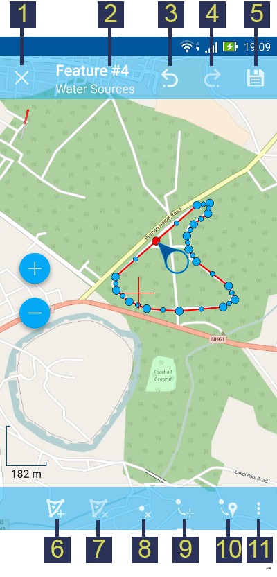
Fig. 962. Editing polygon.#
The numbers indicate: 1 - Quit (without saving); 2 - Feature ID & name of the Layer; 3 - Undo changes; 4 - Redo changes; 5 - Set attributes; 6 - Add hole; 7 - Delete hole; 8 - Delete vertex; 9 - Move vertex to the center of Map screen; 10 - Move vertex to the current location; 11 - Contextual menu with the rest of commands (Append geometry by walk, Append geometry by touch).
When you edit a multipolygon all points included in it change their colour to blue. The selected point will be highlighted in red and have an arrow pointing at it (see Fig. 963.).
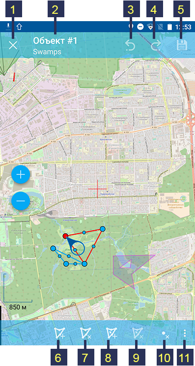
Fig. 963. Editing multipolygon.#
The numbers indicate: 1 - Quit (without saving); 2 - Feature ID & name of the Layer; 3 - Undo changes; 4 - Redo changes; 5 - Set attributes; 6 - Add polygon; 7 - Delete polygon; 8 - Add hole; 9 - Delete hole; 10 - Delete vertex; 11 - Contextual menu with the rest of commands (Move vertex to the center of Map screen, Move vertex to the current location, Append geometry by walk, Append geometry by touch).
You can delete selected point or polygon (item 7 and 10 in Fig. 963.), move a point to a new location simply pulling it or arrow pointing at it to a desired place, to the center of the screen shown as Red Crosshair marker (item 11 in Fig. 963.) or to the current device location (item 11 in Fig. 963.). Also you can add a new polygon to the multipolygon (item 6 in Fig. 963.) and add or delete a hole (item 8 or 9 in Fig. 963.).
Editing attributes#
To start editing attributes first select a layer you want to edit attributes in. Then switch to Edit mode using any of the methods described in Switching to Edit mode section.
After Editing Toolbar is opened tap “Attributes info” button (item 5 in Fig. 948.). This will open Attributes Info panel as shown in Fig. 964. below.
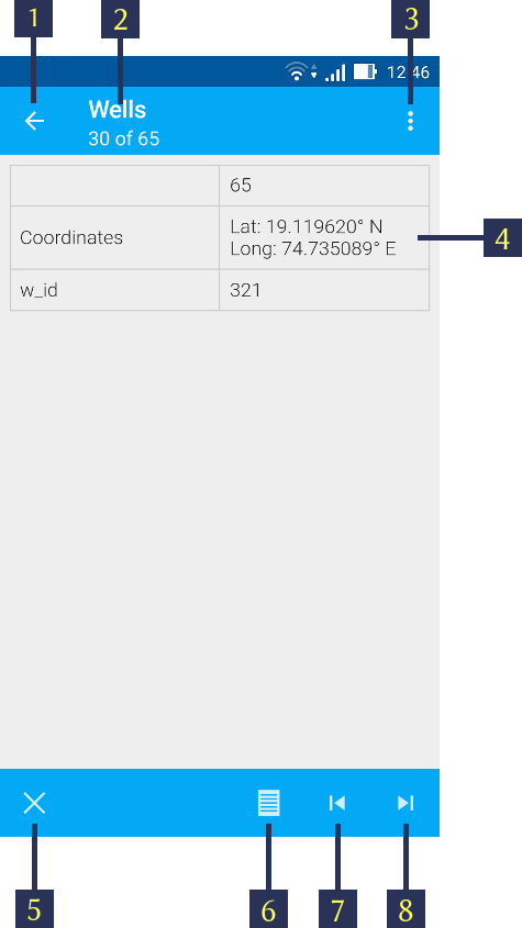
Fig. 964. Attributes Info panel#
The numbers indicate: 1 - Back to previous screen; 2 - Layer name & feature count; 3 - Settings; 4 - Attribute fields; 5 - Close Attributes Info panel; 6 - Set attributes; 7 - Previous record; 8 - Next record.
Note
NextGIS Mobile shows the following attribute fields by default (see item 4 in Fig. 964.):
For Point/Multipoint layers: each point’s location (in Latitude/Longitude).
For Line/Multiline layers: length of each line feature (in meters).
For Polygon/Multipolygon layer: length of each polygon feature’s perimeter (in meters) & area of each polygon feature (in square meters).
Editing attributes using standard form#
To start editing attributes using standard form first tap on “Set attributes” button (see item 6 in Fig. 964.).
This opens a standard Attributes editing form as shown in Fig. 951..
After all the attributes are set tap “Tick” icon in the top right corner (item 2 in Fig. 951.) to save the edits.
Note
If you tap the back button in the top left corner (item 1 in Fig. 951.) instead, the system will warn you about unsaved changes.
The Camera icon at the bottom of a standard Attributes editing form (item 3 in Fig. 951.) allows to add to each feature image files (e.g. photos) from the local storage or take new photos.
Editing attributes using custom form#
If the layer was created from a custom form (NGFP) the custom Attributes editing form will be used for editing. An example of such custom form is shown below in Fig. 965.:
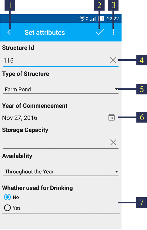
Fig. 965. Custom Attributes editing form.#
The numbers indicate: 1 - Back to previous screen; 2 - Apply changes; 3 - Settings; 4 - Text or Integer field; 5 - Dropdown list; 6 - Date & Datetime; 7 - Radio buttons.
Custom Attributes editing forms may contain the following entry fields:
Text;
Space;
Text field;
List; Tandem list;
Checkbox;
Radio button;
Date Picker;
Photo.
“Text” field is used to provide additional information about geometry feature.
“Space” field is used to increase intervals between fields.
“Text field” can be used to add text or integers, depending on the field type (see item 4 in Fig. 965.).
“List” and “Tandem list” fields are used to store and select values included in custom lists, for example, “List” - region/republic/territory, “Tandem list” - district/area in region/republic/territory (see item 5 in Fig. 965.).
“Checkbox” field allows to check or uncheck a value.
“Date picker” field allows to select date, time or both of them (see item 6 in Fig. 965.).
“Radio button” field allows to select one element from a list of mutually exclusive options (see item 7 in Fig. 965.).
“Photo” field allows to take a new photo or to add photos from the local storage.
After all the attributes are set tap “Tick” icon in the top right corner (item 2 in Fig. 965.) to save the edits.
Note
If you tap the back button in the top left corner (item 1 in Fig. 965.) instead, the system will warn you about unsaved changes.