5.5. Adding resources
NextGIS Web is built on a resource-based approach - each component of the system (layer, group, service) is a resource. One of these resources is a layer - a raster image or vector file (database table).
For each layer you can create an unlimited number of styles - ways of visualizing geodata on a Web Map.
Interface for adding of PostGIS layers, vector and raster layers is practically the same. First, you specify the parameters for the layer, and then you add a style that renders data on the Web Map.
5.5.1. Basemap
In the “Create resource” actions pane click Basemap (Pic. 5.34.). In the opened window enter the name of the resource that will be displayed in the administrator interface (Pic. 5.35.).
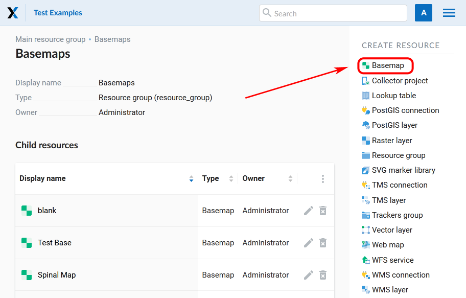
Pic. 5.34. Selection of “Basemap” action
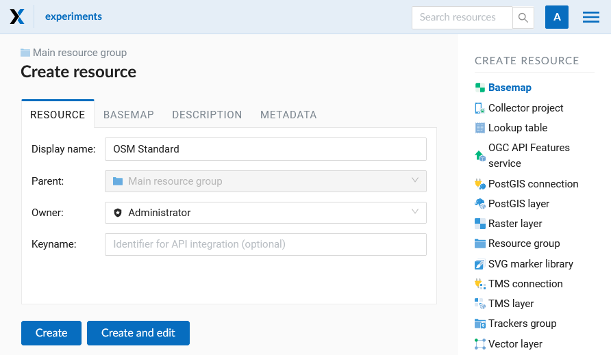
Pic. 5.35. Basemap name
The “Description” and “Metadata” of the resource are configured on the corresponding tabs (Pic. 5.36.). On the “Description” tab you can add any text describing the content.

Pic. 5.36. Basemap description
In the “Basemap” tab you must enter the URL-address of the TMS service (Pic. 5.37.). There are two ways to do so:
Use the search bar to find a map in the QuickMapServices catalog. After a map is selected, URL field will be filled in automatically and option “Use options from QMS” will be activated.
Enter the address manually. Works if the QMS flag is unchecked.
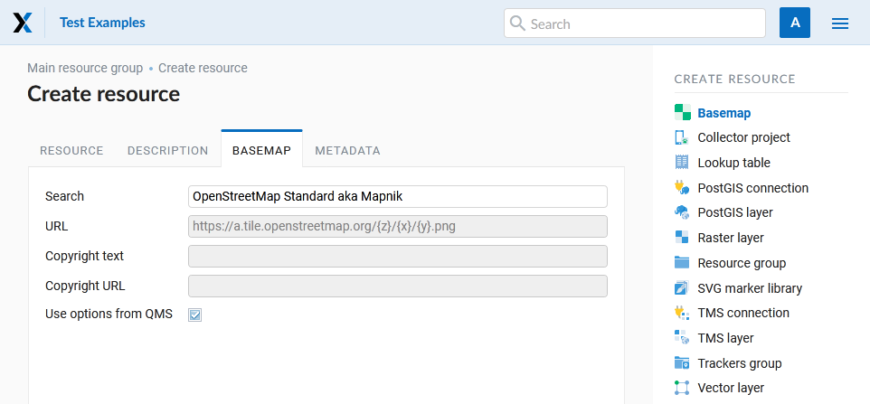
Pic. 5.37. Basemap settings
5.5.2. Data Preview
The preview function allows you to see the uploaded data on the basemap without adding it on the Web Map.
Note
For vector data, previews are available for both the layer and the style. For rasters - for style only. For TMS and WFS layers, preview is also available.
While in the corresponding resource, click the “eye” icon opposite the name of the child resource or the Preview button in the right menu in the Extra section.
A visual preview of the uploaded geometries will open without the possibility of more detailed interaction (viewing attributes, identifying objects, etc).
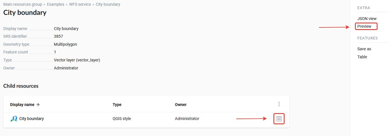
Pic. 5.38. Selecting Data Preview Function
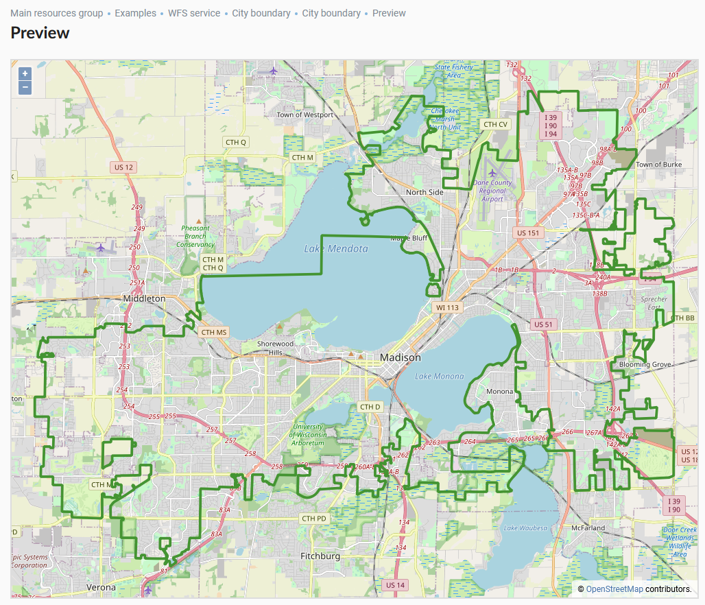
Pic. 5.39. Data preview
5.5.3. Raster layer
Raster images in NextGIS Web should be loaded using the “Raster Layer” special resource.
5.5.3.1. Creation process
To add a raster layer navigate to a group where you want to create it. In the “Create resource” actions pane click Raster layer (see Pic. 5.40.).
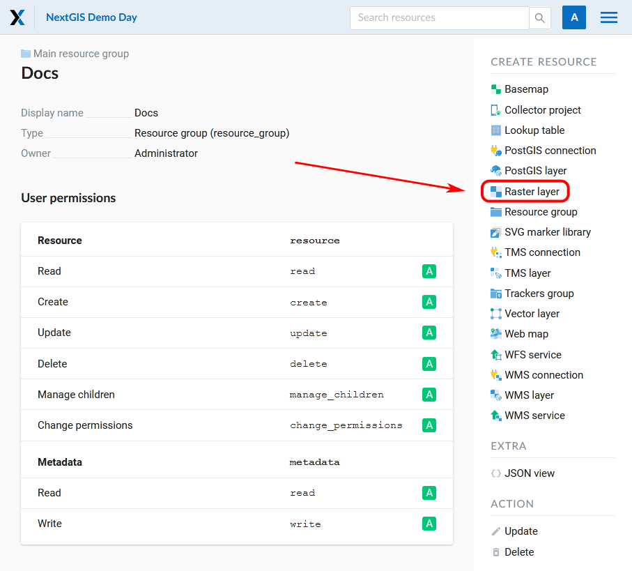
Pic. 5.40. Selection of “Raster layer” action
On the “Raster layer” tab you need to upload a geodata file in GeoTIFF format. The upload dialog indicates the maximum file size allowed on your subscription plan (Pic. 5.41.).
If you plan to use this raster in QGIS directly from your Web GIS, tick the Upload as Cloud Optimized GeoTIFF (COG) checkbox. This will optimize the raster to ensure fast display.

Pic. 5.41. Uploading raster file
In the “Resource” tab specify the name of the raster layer (see Pic. 5.42.). It will be displayed in the admin interface. The “Key” field is optional.

Pic. 5.42. Raster layer name
On the “Description” tab you can add any text describing the content of this layer (Pic. 5.43.).
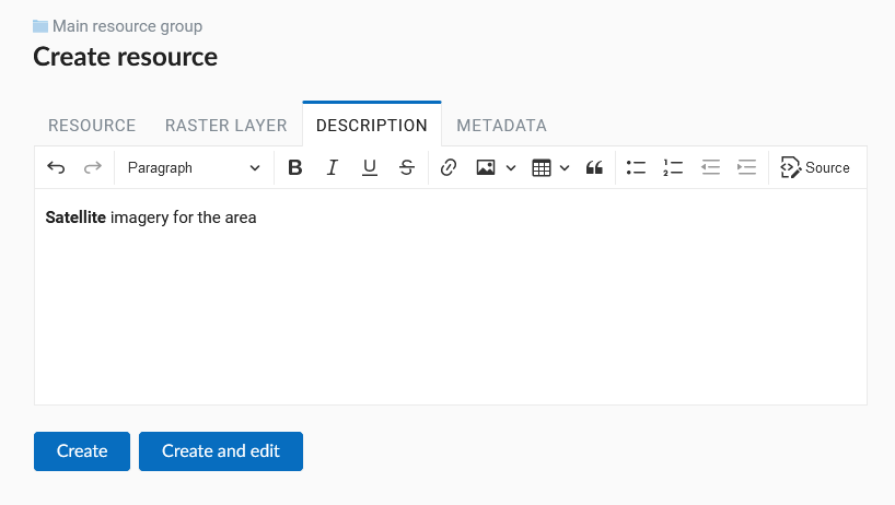
Pic. 5.43. Raster layer description
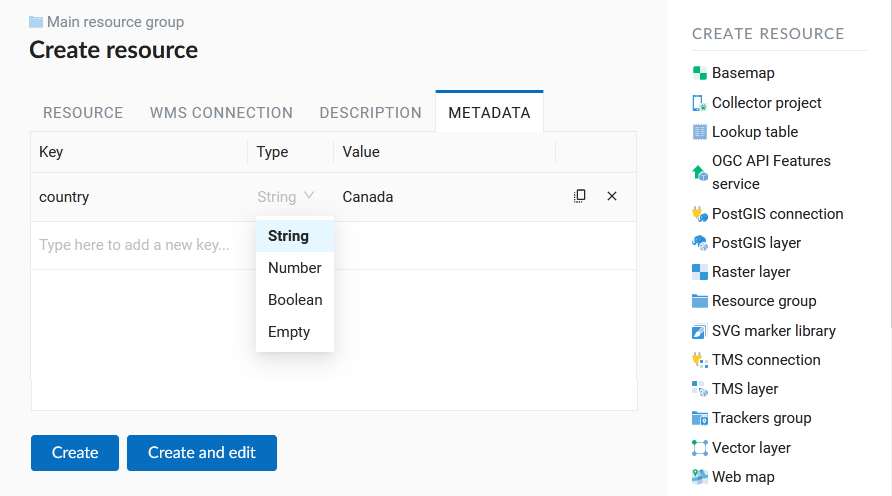
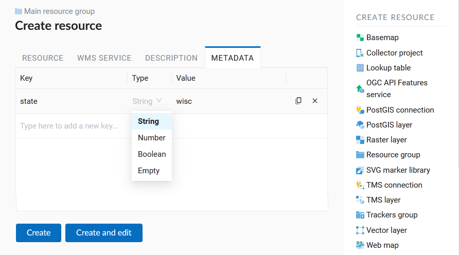
In the “Metadata” tab you can enter information in the “key-value” format (Pic. 5.44.).
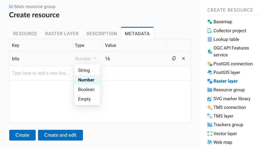
Pic. 5.44. Raster layer metadata
To complete click the Create button.
5.5.3.2. Raster style (QGIS)
After a raster file is successfully uploaded and a raster layer is created, you need to create a QGIS style. This procedure is similar to adding a vector layer style. You can create one in NextGIS QGIS. You will need this style to add the raster to a Web Map when creating one (for more information see subsection Creating a Web Map).
5.5.3.3. Raster layer with transparency (clip or alpha channel)
Most of utilities do not create an alpha channel and only add a NoData value. To transform NoData value to an alpha channel use the command line utility gdalwarp. Here is an example of this command.
gdalwarp -t_srs EPSG:3857 -multi -dstalpha -dstnodata none -wo \
"UNIFIED_SRC_NODATA=YES" -co COMPRESS=JPEG \
d:\temp\o\ast_20010730_010043_rgb.tif d:\temp\o\ast_20010730_010043_rgba.tif
5.5.3.4. Uploading Indexed Color Rasters
Indexed Color raster files are uploaded just like the RGB raster files. If the file is not in GeoTIFF format, you can convert it as follows:
gdal_translate yaroslavl.map yaroslavl.tif
5.5.4. Vector layer from file
You can create vector layers based on ESRI Shapefile, GeoJSON, KML, CSV, GML and GeoPackage formats in NextGIS Web.
5.5.4.1. Creation process
Navigate to the resource group (folder) in which to create a vector layer. In the “Create resource” actions pane select Vector layer (see Pic. 5.45.).
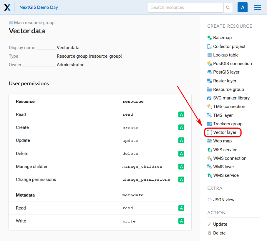
Pic. 5.45. Selection of “Vector layer” action
In the opened tab you need to upload a geodata file in ESRI Shapefile (zip-archive), GeoJSON, KML, GML or GeoPackage format. The upload dialog indicates the maximum file size allowed on your subscription plan (Pic. 5.46.). Web GIS can process multi-layer datasets. If an archive contains several layers, then after it is uploaded, you will be asked to select which layer will be used for creating Vector layer resource.
Below it is proposed to define advanced options for creating a vector layer. Depending on the quality of the data you can handle geometry errors when uploading a file as follows:
Not fix errors
Fix whatever is possible
Fix without losing data
Next - the type of geometry, the presence/absence of multigeometries, Z-coordinates and the source of the FID (FID field, determine automatically or indicate from a particular field) are indicated. More about advanced options.
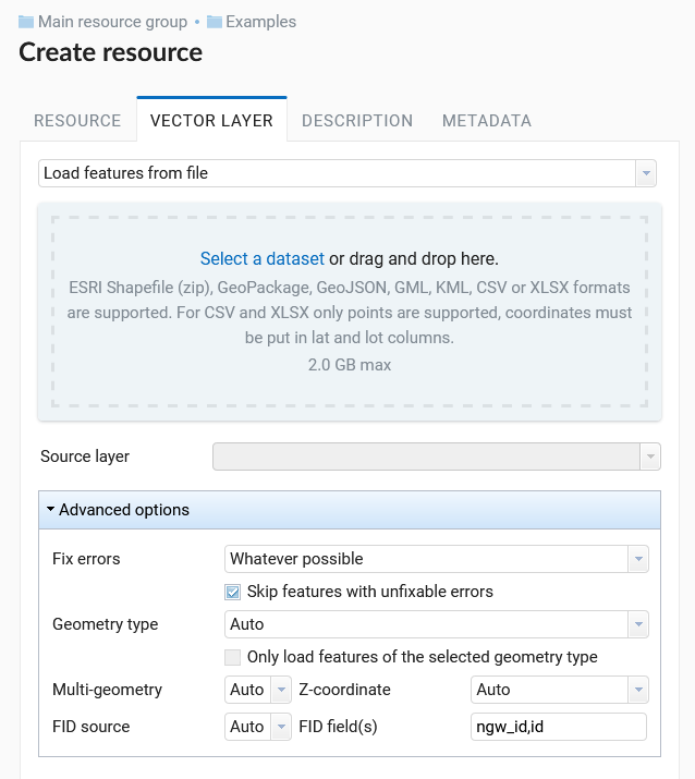
Pic. 5.46. Vector file upload tab
In the “Resource” tab enter the name of the vector layer (Pic. 5.47.). It will be displayed in the admin interface. The “Key” field is optional.

Pic. 5.47. Vector layer name
In the “Description” tab you can add any text describing the content of this layer (Pic. 5.48.).

Pic. 5.48. Vector layer description
In the “Metadata” tab you can add information in the “key-value” format (Pic. 5.49.).

Pic. 5.49. Vector layer metadata
After uploading the file and specifying the parameters, click the Create button.
Then you can create a style that will later visualize the data layer on a Web Map.
5.5.4.2. Input data requirements
Source files could be in the following formats:
Use NextGIS Connect if you need to upload data in other formats.
Note
In case of ESRI Shapefile, all components (dbf, shp, shx, prj and other files) should be compressed to a zip-archive.
Warning
Avoid using Unicode symbols in data field names. While such data can be uploaded to the Web GIS and displayed on Web Maps, you can experience problems working with it in NextGIS Mobile or visualization (especially if labels are using such fields). Use plain Latin for field names and set up field aliases to show Unicode names.
If input data layer contains fields named id (ID) or geom (GEOM), they will be renamed on import. If id has meaningful identifiers, they will automatically be turned into internal FIDs.
5.5.5. Empty vector layer
Creating an empty vector layer allows you to start a data base in your WebGIS without using a desktop app.
Navigate to the resource group (folder) in which to create a vector layer. In the “Create resource” actions pane select Vector layer (see Pic. 5.50.).
Pic. 5.50. Selecting “Vector layer” action
In the opened window use the dropdown menu to select “Create empty layer”. In the field below select geometry type for the layer. By default, a point layer will be created.
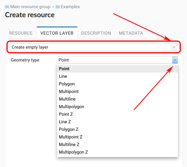
Pic. 5.51. Selecting geometry type for an empty layer
In the “Resource” tab enter the name of the vector layer (Pic. 5.47.). It will be displayed in the admin interface. The “Key” field is optional.
In the “Description” tab you can add any text describing the content (Pic. 5.48.).
In the “Metadata” tab you can add information in the “key-value” format (Pic. 5.49.).
After uploading the file and specifying the parameters, click the Create button.
Then you can create a style that will later visualize the data layer on a Web Map.
To add features to the newly created layer you can use the editing toolbar.
5.5.6. Vector layer from PostGIS
To add a vector layer from PostgreSQL database with PostGIS extension, you need to create a PostGIS connection resource. It is enough to create one connection.
5.5.6.1. Creating PostGIS connection
In the “Create resource” actions pane click PostGIS connection (see Pic. 5.52.).

Pic. 5.52. Selection of “PostGIS connection” action
Enter a display name that will be visible in the administrator interface. Not to be confused with layer name in a database.
“Keyname” field is optional.

Pic. 5.53. Create resource dialog for PostGIS connection
You can also add resource description and metadata on the corresponding tabs.
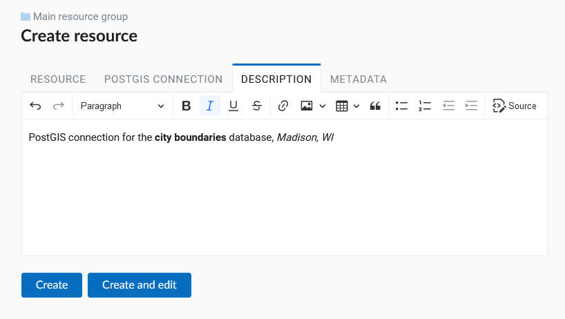
Pic. 5.54. PostGIS connection description
Pic. 5.55. PostGIS connection metadata
Switch from “Resource” to “PostGIS connection” tab, which is presented on Pic. 5.56..
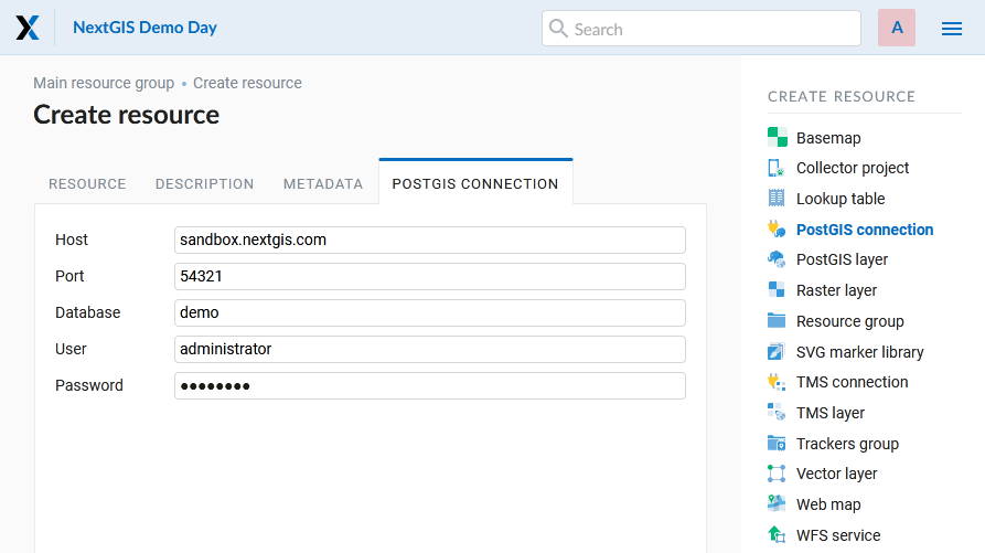
Pic. 5.56. PostGIS connection tab of Create resource dialog
In this tab you should enter connection parameters for the PostGIS database that you are going to take data from. Then click Create.
5.5.6.2. Creating PostGIS layer
Now you can add individual PostGIS layers. Navigate to a group where you want to create layers and in the “Create resource” actions pane select PostGIS layer (see Pic. 5.57.).
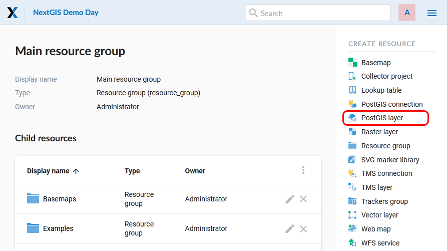
Pic. 5.57. Selection of “PostGIS layer” action

Pic. 5.58. Create resource dialog for PostGIS layer
Enter a display name that will be visible in administrator interface and in the map layer tree.
“Keyname” field is optional.
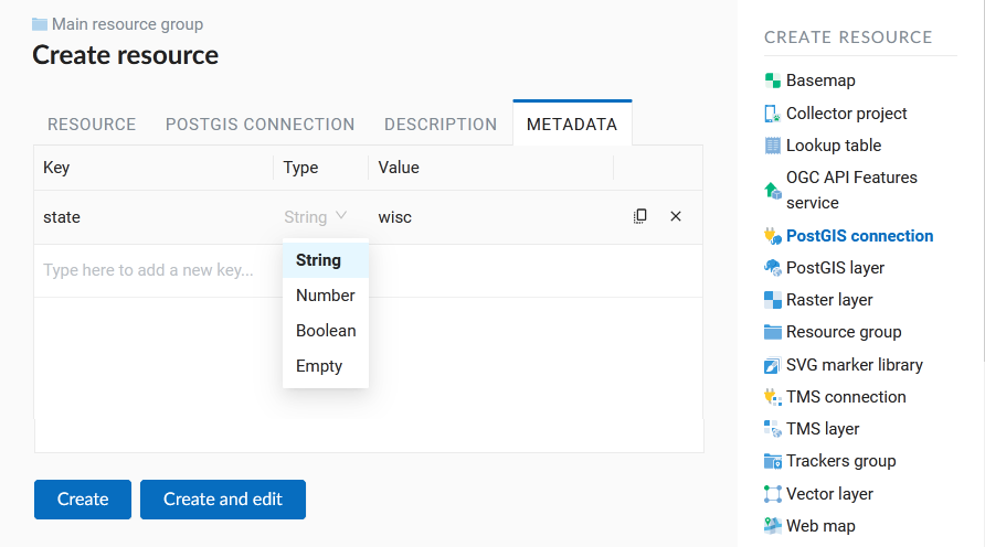
You can also add resource description and metadata on the corresponding tabs.
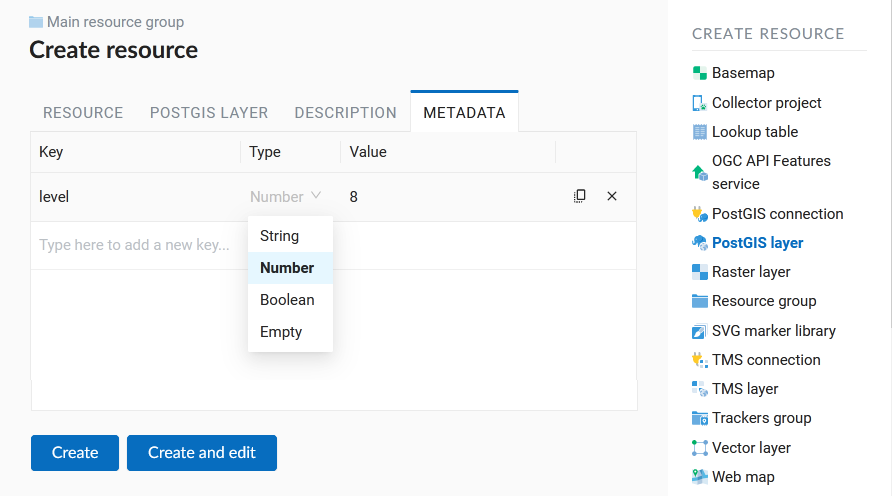
Pic. 5.59. PostGIS layer metadata
Switch from “Resource” tab to “PostGIS layer” tab, which is presented on Pic. 5.60..
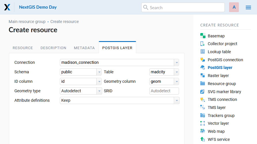
Pic. 5.60. PostGIS layer tab of create resource dialog
Then perform the following steps:
From a dropdown list select a database connection (creation of a connection is described above).
Select a schema of the database where layer data is stored. A single database can store multiple schemas. Each schema contains tables and views. If there is only one schema, it’s called public. For more information see PostgreSQL DBMS manual.
Select the Table name (PostGIS layer). You need to know names of tables and columns in your database. Display of tables content is not a feature of NextGIS Web. You can view them using NextGIS QGIS or pgAdmin software.
Select an ID column. When data is loaded into PostGIS using NextGIS QGIS software, an ogc_fid column is created. If the data was loaded another way, the column name may be different. An ID column should follow rules for data type: the value type should be a number (numeric) and it should be a primary key.
Select the Geometry column (if the data was loaded to PostGIS using NextGIS QGIS software, usually a geometry column called wkb_geometry is created. If the data was loaded some other way, the name of the column may be different).
Parameters “Geometry type”, “Attribute definitions” and “SRID” are not required, so you can use default values.
After specifying all the necessery parameters, click Create.
5.5.6.3. Details
NextGIS Web software supports tables with point, line and polygon geometries stored in a single geometry column. This is required for some specific datasets: e.g. if one table stores coordinates for parks as polygons and trash cans as points. In this case, in NextGIS Web you need to add three different layers, one for each type of geometry, and select the appropriate “Geometry type” parameter for each layer.
After a layer is created, you need to set a label attribute to display labels. Navigate to layer edit dialog and set a checkbox for the required field in the “Label attribute” column.
If the structure of the database changes (column names, column types, number of columns, table names etc.), you need to update the attribute definitions in the layer properties. Select “Update” in the actions pane and then on the “PostGIS layer” tab change “Attribute definitions” to “Reload” and click Save.
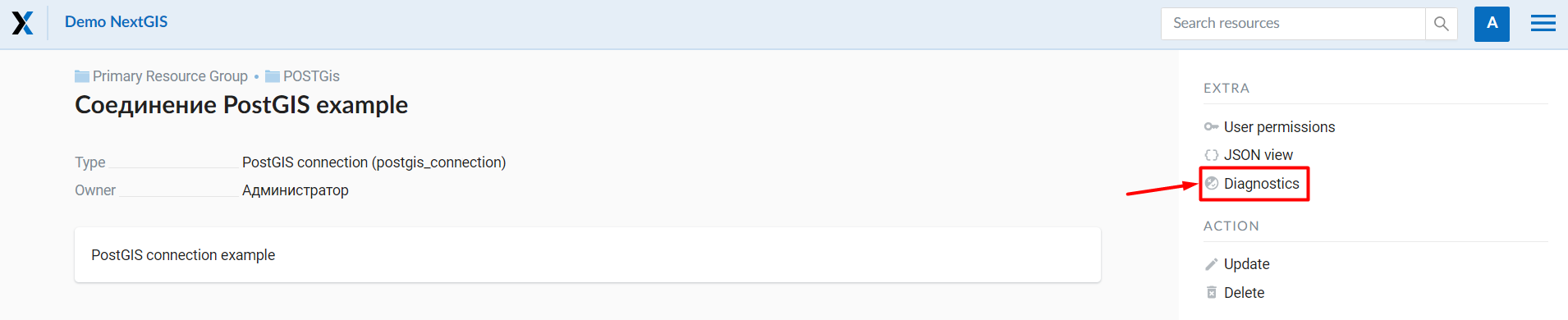
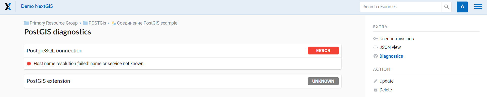
5.5.6.4. PostGIS diagnostics
You can check the correctness of the entered data when adding the PostGIS Connection resource using the Diagnostics tool. To do this, you need to click on the Diagnostics button on the panel on the right.
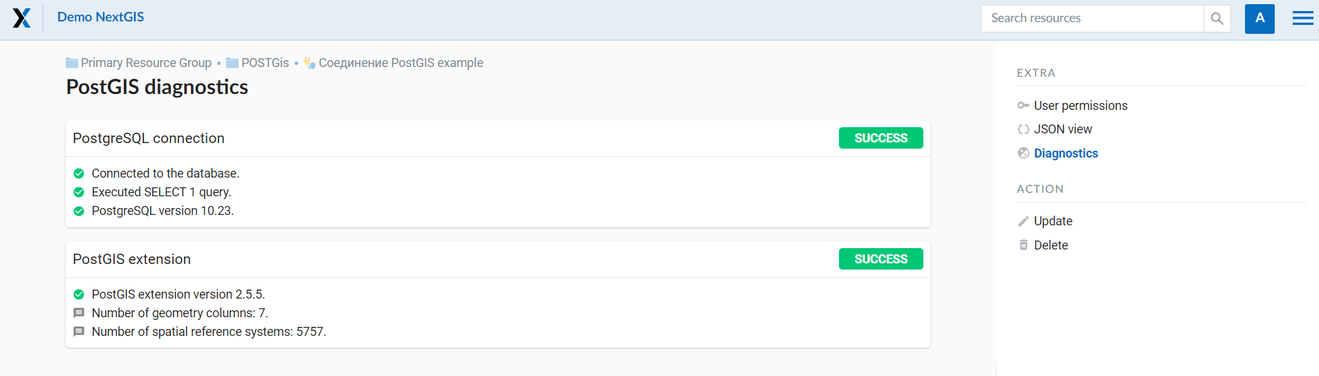
If all fields are filled in correctly when creating a connection to PostGIS - diagnostics will be successful.
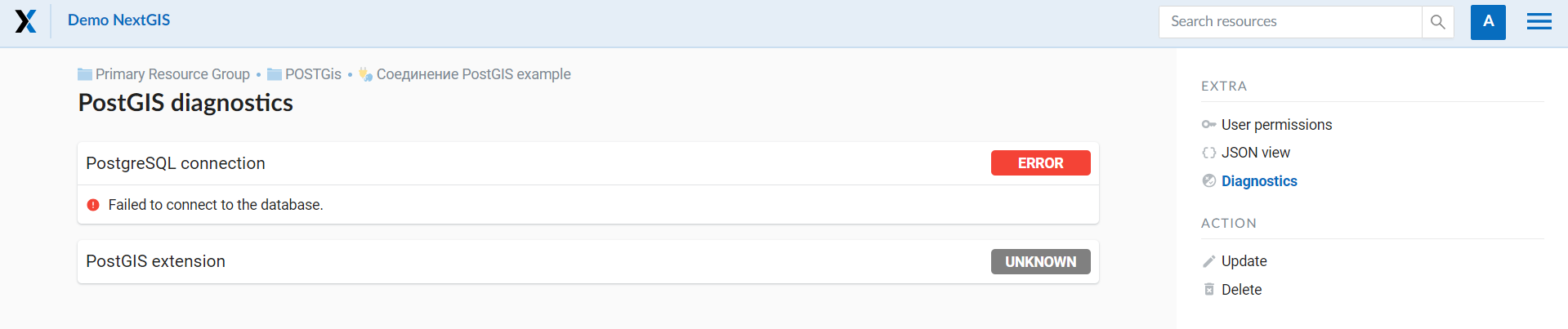
If any of the entered data is not correct, an error message will appear.
5.5.6.5. PostGIS layer troubleshooting
You created a connection, but when you try to create a PostGIS layer based on it, you get errors.
If you get:
Cannot connect to the database!
Check the database: is it available, do you have the right credentials? You can do it using pgAdmin or NextGIS QGIS.
Note that databases may be down temporarily and credentials might change.
5.5.6.6. Create layers with conditions
In NextGIS Web you can not define queries using WHERE SQL clause. This provides additional security (prevention of SQL Injection attack). To provide query capability you need to create views with appropriate queries in the database.
To do this connect to PostgreSQL/PostGIS database using pgAdmin, then navigate to data schema where you want to create a view, right click tree item “Views” and select “New view” (see item 1 in Pic. 5.61.). Also you can right click on schema name and select “New object” and then “New view”. In the opened dialog, enter the following information:
View name («Properties» tab).
Data schema where to create a view («Properties» tab).
SQL query («Definition» tab).
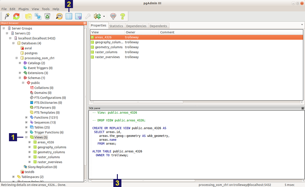
Pic. 5.61. Main dialog of pgAdmin software
The numbers indicate: 1. – Database items tree; 2 – a button for table open (is active if a table is selected in tree); 3 – SQL query for view.
After that you can display a view to check if the query is correct without closing pgAdmin (see item 2 in Pic. 5.61.).
5.5.7. WMS layer
Note
Currently supported WMS versions 1.1.1 and 1.3.0.
NextGIS Web is a WMS client. To connect a WMS layer you need to know its address. WMS server should be able to serve it using a coordinate system EPSG:3857. You can check if this coordinate system is available for a particular layer by making a GetCapabilites request to a server and examining the response. For example a WMS layer provided by Geofabrik (GetCapabilities), responds in EPSG:4326 and EPSG:900913. While EPSG:900913 and EPSG:3857 are technically the same, NextGIS Web requests data in EPSG:3857 and this particular server does not support that coordinate system.
5.5.7.1. Creating WMS Connection
To add a WMS layer you need to create a resource called WMS connection. You may create a single connection for many layers. In the “Create resource” actions pane click WMS connection (see Pic. 5.62.).
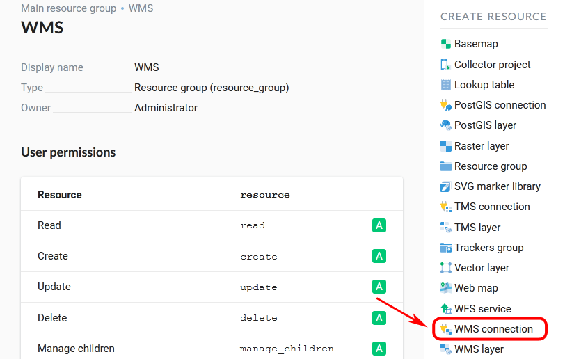
Pic. 5.62. Selection of “WMS connection” action
Create resource dialog for WMS connection is presented on Pic. 5.63..

Pic. 5.63. Create resource dialog for WMS connection
Enter the name of the resource that will be displayed in the administrator interface. Not to be confused with layer name in a database. “Keyname” field is optional.
On the “Description” tab you can add any text describing the content of this connection.
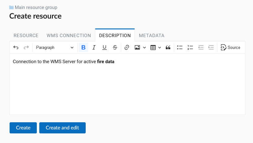
Pic. 5.64. WMS connection description
On the “Metadata” tab you can enter information in the “key-value” format.
Pic. 5.65. WMS connection metadata
Switch to “WMS connection” tab, which is presented on Pic. 5.66..
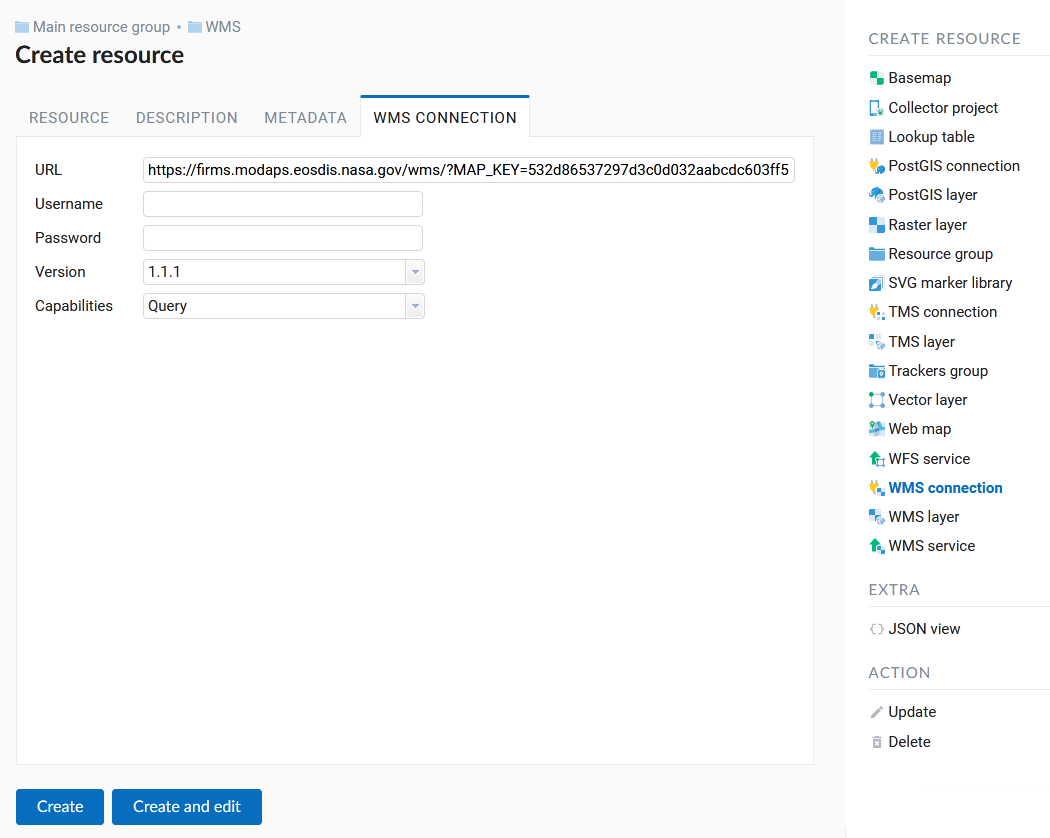
Pic. 5.66. WMS connection tab of Create resource dialog
Here enter the following WMS server connection parameters:
URL
Username
Password
Version of WMS protocol
Capabilities (manages GetCapabilities queries to the WMS Server)
Supported versions of WMS protocol: 1.1.1, 1.3.0 After setting up all necessery parameters, click Create.
5.5.7.2. Creating WMS Layer
Now you can add individual WMS layers. Navigate to a group where you want to create WMS layers and in the “Create resource” actions pane select WMS layer (see Pic. 5.67.).
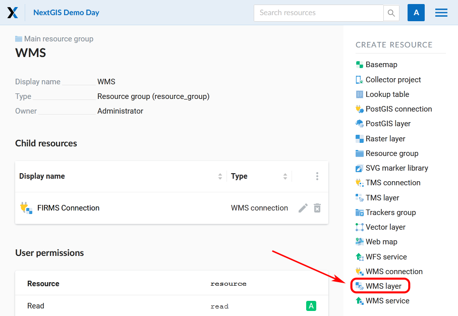
Pic. 5.67. Selection of “WMS layer” action
Create resource dialog for WMS layer is presented on Pic. 5.68.

Pic. 5.68. Create resource dialog for WMS layer
Enter display name that will be visible in administrator interface and in the map layer tree.
“Keyname” field is optional.
Tile cache settings are described in detail in this section.
On the “Description” tab you can add any text describing the content of this layer.

Pic. 5.69. WMS layer description
OIn the “Metadata” tab you can enter information in the “key-value” format.
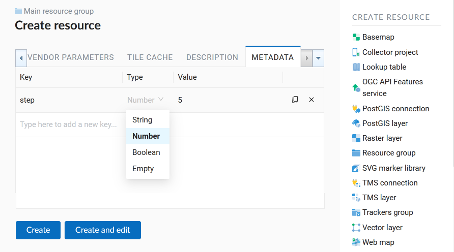
Pic. 5.70. WMS layer metadata
Switch to the “WMS layer” tab, which is presented on Pic. 5.71. and perform the following steps:
Select the WMS connection that was created earlier.
Select the appropriate MIME-type from the dropdown list.
Select the required layers from the list by clicking the underlined names. You can select several layers.
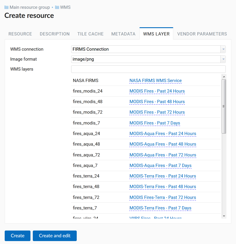
Pic. 5.71. WMS layer tab of Create resource dialog
In the last tab you can add vendor parameters. These are special query settings for additional functions. They vary depending on the WMS provider.
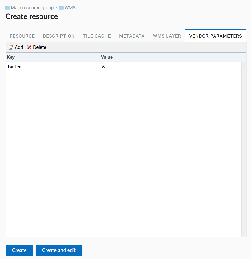
Pic. 5.72. Vendor parameters of the WMS layer
After configuring all the parameters click Create.
Warning
Identification requests to external WMS layers from Web Maps are not supported yet.
5.5.8. WMS service
NextGIS Web software can perform as WMS server. This protocol is used to provide images with a requested extent.
To deploy a WMS service you need to add a resource. In the “Create resource” actions pane click WMS service (see Pic. 5.73.).
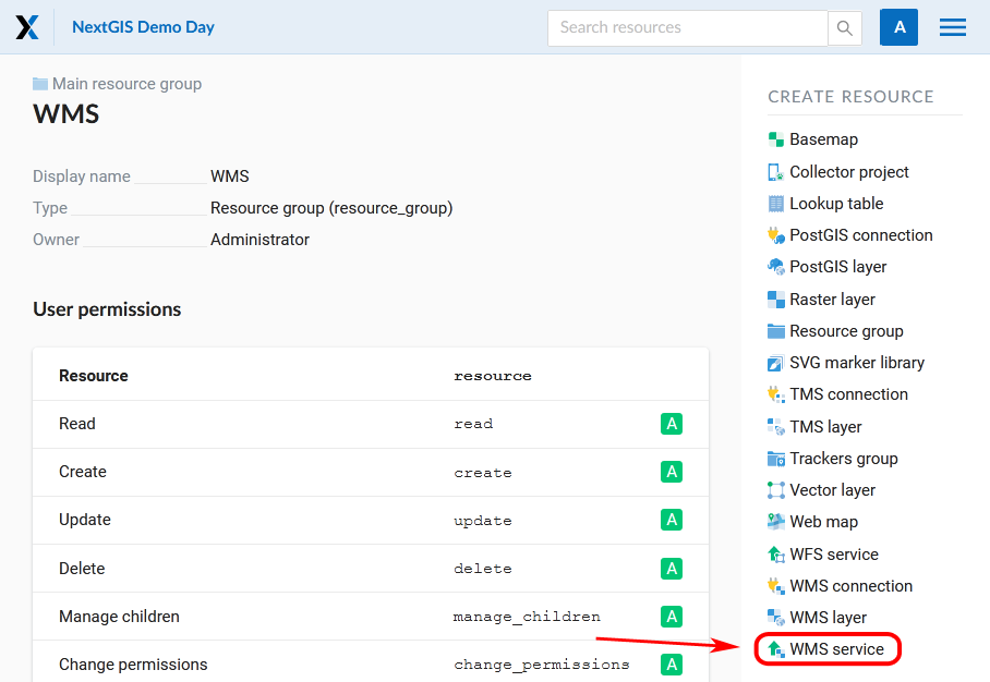
Pic. 5.73. Selection of “WMS service” action
Create resource dialog for WMS service is presented on Pic. 5.74..

Pic. 5.74. Create resource dialog for WMS service
Enter the name of the resource that will be displayed in the administrator interface. Do not confuse this name with a name of layers in a database.
“Keyname” field is optional.
On the “Description” tab you can add any text describing the content of this service.
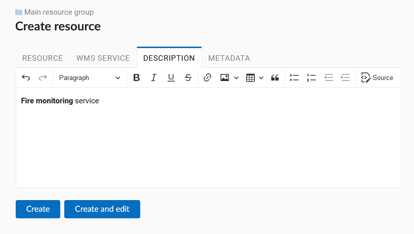
Pic. 5.75. WMS service description
On the “Metadata” tab you can enter information in the “key-value” format.
Pic. 5.76. WMS service metadata
Switch to “WMS service” tab, which is presented on Pic. 5.77.. Here add links to required layers or layer styles. You can also set the min and max scale for the data visualisation.

Pic. 5.77. WMS service tab of Create resource dialog
After the resource is created, you will see a message with the WMS service URL which you can use in other software, e.g. NextGIS QGIS or JOSM. Then you need to set access permissions for the WMS service (see Access management).
NextGIS Web layer can be added to desktop, mobile and Web GIS in different ways.
5.5.8.1. Using WMS service connection
NextGIS Web acts as a WMS server: WMS services created in NextGIS Web can be added to any software that supports WMS protocol. For that you need to know the WMS service URL. You can get it on the WMS service page. The link may look like this:
https://demo.nextgis.com/api/resource/4817/wms?
To use WMS service through GDAL utilities you need to create an XML file for the required layer. Enter these parameters to the ServerUrl string in example below. The rest remains unchanged.
<GDAL_WMS>
 <Service name="WMS">
     <Version>1.1.1</Version>
     <ServerUrl>https://demo.nextgis.com/api/resource/4817/wms?</ServerUrl>
     <SRS>EPSG:3857</SRS>
     <ImageFormat>image/png</ImageFormat>
     <Layers>moscow_boundary_multipolygon</Layers>
     <Styles></Styles>
 </Service>
 <DataWindow>
   <UpperLeftX>-20037508.34</UpperLeftX>
   <UpperLeftY>20037508.34</UpperLeftY>
   <LowerRightX>20037508.34</LowerRightX>
   <LowerRightY>-20037508.34</LowerRightY>
   <SizeY>40075016</SizeY>
   <SizeX>40075016.857</SizeX>
 </DataWindow>
 <Projection>EPSG:3857</Projection>
 <BandsCount>3</BandsCount>
</GDAL_WMS>
If you need an image with transparency (alpha channel) set <BandsCount>4</BandsCount>.
Here is an example of a GDAL command. The utility gets an image by WMS from NextGIS Web and saves it to a GeoTIFF format.
$ gdal_translate -of "GTIFF" -outsize 1000 0  -projwin  4143247 7497160 \
4190083 7468902   ngw.xml test.tiff
5.5.9. TMS layer
5.5.9.1. TMS Connection
Similarly to WMS, to add a TMS layer, you first need to create a TMS connection. Select TMS connection in the “Create resource” actions pane (see Pic. 5.78.)
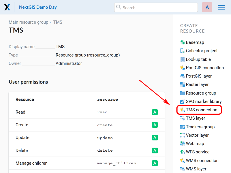
Pic. 5.78. Selecting a TMS Connection resource
Enter the connection name that will be displayed in the administrator interface (see Pic. 5.79.).

Pic. 5.79. TMS Connection Resource Name
The “Key” field is optional. If needed, you can also add a description and metadata. In the TMS connection tab you need to select the way to connect to the TMS server - custom or via NextGIS geoservices (see Pic. 5.80.).
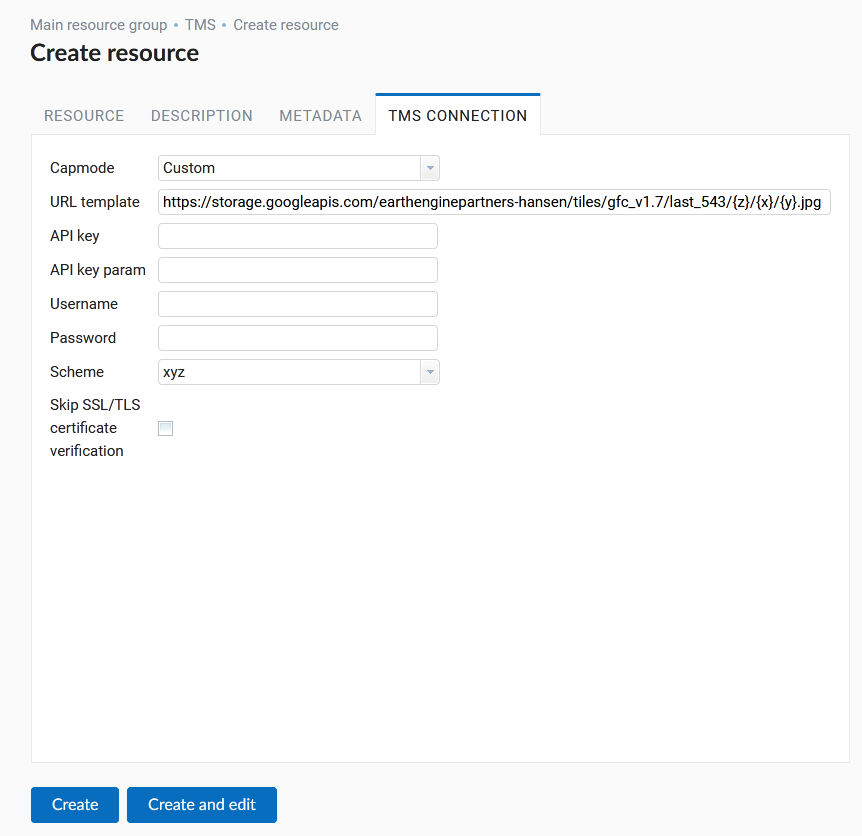
Pic. 5.80. Configuring TMS Connection
In the case of a custom connection method, the user must specify the URL template, API key parameters if needed and the tile scheme used. For NextGIS geoservices, only a custom API key is specified. After filling in all fields press Create to complete the process of creating a TMS Connection resource.
5.5.9.2. TMS layer
TMS layer resource is created using previously created TMS Connection. Select TMS layer in the “Create resource” actions pane (see Pic. 5.81.).
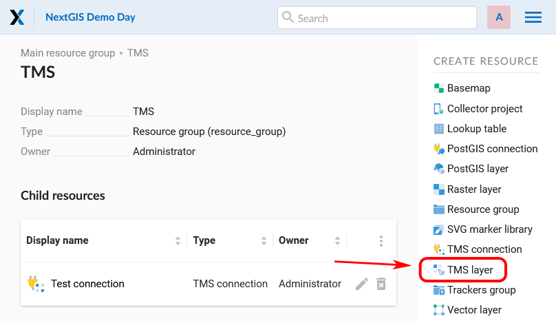
Pic. 5.81. Selecting of TMS layer action
Enter the name that will be displayed in the administrator interface (see Pic. 5.82.).

Pic. 5.82. TMS layer name
Caching provides faster rendering of Web Map layers. Tile cache settings are described in details in this section.
The main display settings are on the TMS layer tab (см. Pic. 5.83.):
TMS connection - select a TMS connection resource that was created earlier
Select coordinate system for data display
The range of zoom levels for data display
Extent in degrees
Tile size in pixels
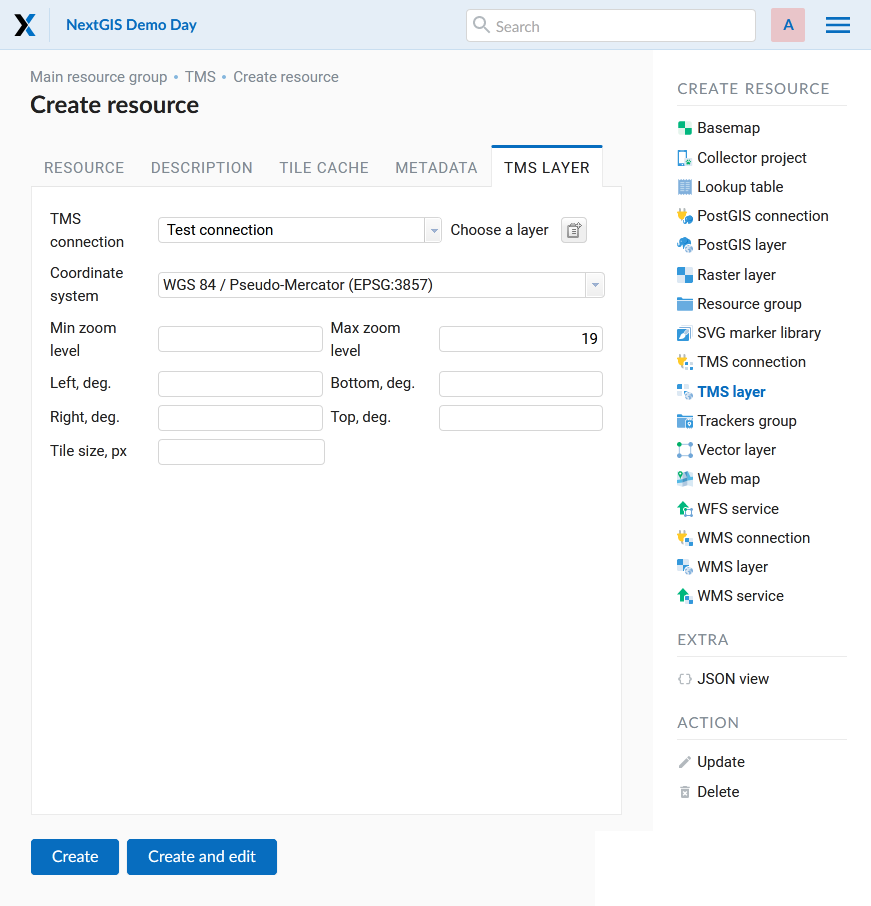
Pic. 5.83. TMS layer settings
After creating a TMS layer, the user can add it to the Web Map to display. No style is needed.
5.5.9.3. Using TMS service
NextGIS Web is a TMS server. Layers and styles created in it can be accessed via any software supporting TMS protocol. You will need the URL for the TMS service.
The link should look like this:
https://demo.nextgis.com/api/component/render/tile?z={z}&x={x}&y={y}&resource=234
To use TMS service through GDAL utilities you need to create an XML file. You will need the TMS link. Enter these parameters to ServerUrl string in example below. The rest remains unchanged.
<GDAL_WMS>
 <Service name="TMS">
     <ServerUrl>https://demo.nextgis.com/api/component/render/tile?z={z}&x={x}&y={y}&resource=234
     </ServerUrl>
 </Service>
 <DataWindow>
     <UpperLeftX>-20037508.34</UpperLeftX>
     <UpperLeftY>20037508.34</UpperLeftY>
     <LowerRightX>20037508.34</LowerRightX>
     <LowerRightY>-20037508.34</LowerRightY>
     <TileLevel>18</TileLevel>
     <TileCountX>1</TileCountX>
     <TileCountY>1</TileCountY>
     <YOrigin>top</YOrigin>
 </DataWindow>
 <Projection>EPSG:3857</Projection>
 <BlockSizeX>256</BlockSizeX>
 <BlockSizeY>256</BlockSizeY>
 <BandsCount>4</BandsCount>
 <Cache />
</GDAL_WMS>
5.5.10. Tileset
To add a Tileset, select a Tileset in the “Create Resource” block of operations.
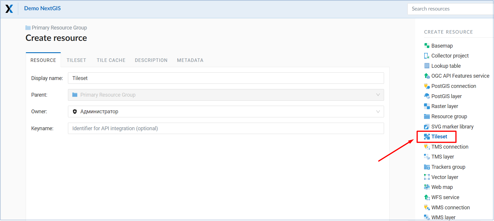
Next, you need to enter the name of the tileset, which will be displayed in the administrative web interface.
The “Key” field is optional. On the appropriate tabs, you can add a resource description and metadata. Typically, metadata is used to develop third-party applications using APIs.
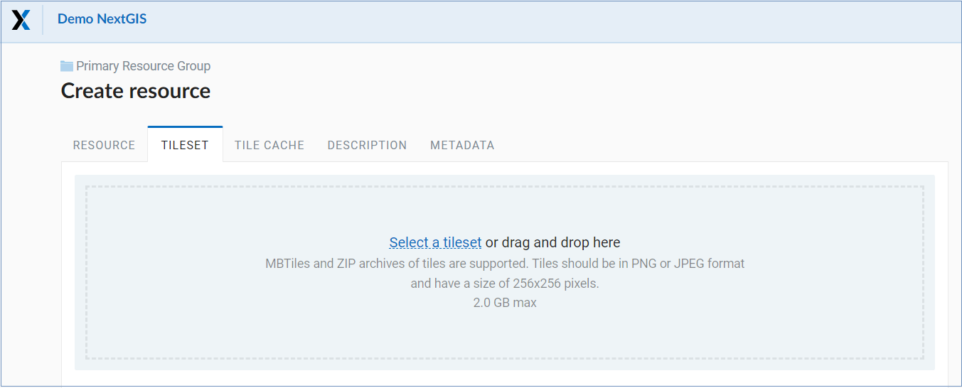
In the “Tileset” tab, you need to upload a tileset in MBTiles format or a zip archive. Tiles must be in PNG or JPEG format and have a size of 256x256 pixels.
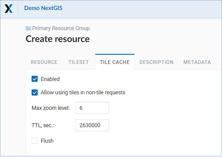
In the “Tile Cache” tab, the user can set the caching settings:
Enable - enable/disable tile caching;
Allow using tiles in non-tile requests - when requesting an image (not a tile), use cached tiles if available;
Max zoom level - the threshold value above which the cache is not accessed, the map image is rendered on the fly;
TTL, sec (Time to live) - “time to live” or storage of tiles on the server in seconds, after which the image will be re-formed at the next request. If TTL = 0, then the storage time of tiles is not limited;
Flush - write only - clears the tile cache when saving the style.
After filling in all the fields, clicking the Create button completes the process of creating the resource Tileset.
5.5.11. WFS service
WFS layer setup is performed the same way as for WMS service but you add layers instead of styles.
Note
Currently supported filters are Intersects, ResourceId (ObjectId, FeatureId).
NextGIS Web acts as WFS server and publishes WFS services based on vector layers. Third party software can use these services to edit vector data on server. Supported WFS protocol versions are 1.0, 1.1, 2.0, 2.0.2.
To deploy a WFS service click WFS service in the “Create resource” actions pane (see Pic. 5.84.).
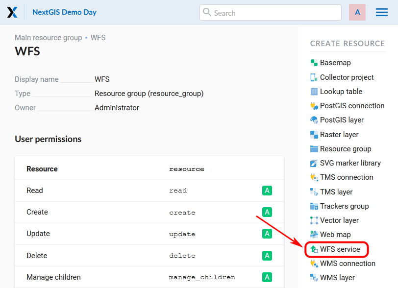
Pic. 5.84. Selection of “WFS service” action
Create resource dialog for WFS service is presented on Pic. 5.85..

Pic. 5.85. Create resource dialog for WFS service
Enter the name of the resource that will be displayed in the administrator interface. Do not confuse this name with a name of layers in a database.
“Keyname” field is optional.
On the “Description” tab you can add any text describing the content of this service.

Pic. 5.86. WFS service description
On the “Metadata” tab you can enter information in the “key-value” format.
Pic. 5.87. WFS service metadata
Switch to “WFS service” tab, which is presented on Pic. 5.88. and add required layers to a list (see Pic. 5.88.). For each layer you can set a limit for the number of features returned from the vector layer. By default the value is 1000. If this parameter is set to empty, the limit will be disabled and all features will be returned to the client. This may result in high server load and significant timeouts in case of large data volume.

Pic. 5.88. WFS service tab of Create resource dialog
5.5.11.1. Using WFS service
After the resource is created, a URL for the WFS service is available. You can use it in other software, for example NextGIS QGIS.
You can set access permissions for WFS service if needed. See section Access management.
WFS services can also be accessed with links of the following type (basic auth is supported):
https://mywebgis.nextgis.com/api/resource/2413/wfs?SERVICE=WFS&TYPENAME=ngw_id_2412&username=administrator&password=mypassword&srsname=EPSG:3857&VERSION=1.0.0&REQUEST=GetFeature
5.5.12. OGC API Features service
The OGC API Features service is configured in the same way as for a WFS service.
NextGIS Web acts as OGC API Features server and publishes OGC API Features services based on vector layers. Third party software can use these services to edit vector data on server. Supported OGC API Features protocol versions is 1.0.0.
To deploy a OGC API Features service click OGC API Features service in the “Create resource” actions pane (see Pic. 5.89.).
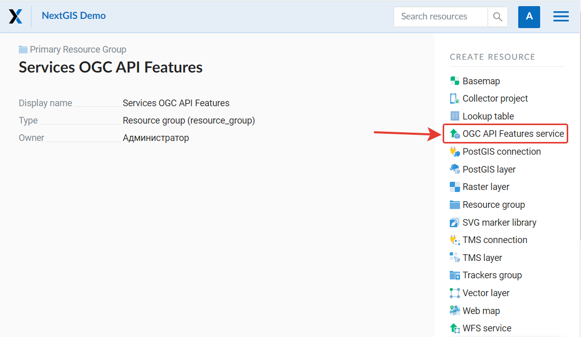
Pic. 5.89. Selection of “OGC API Features service” action
Create resource dialog for OGC API Features service is presented on Pic. 5.90..
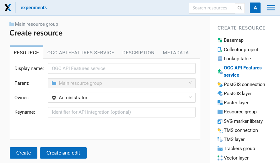
Pic. 5.90. Create resource dialog for OGC API Features service
Enter the name of the resource that will be displayed in the administrator interface. Do not confuse this name with a name of layers in a database.
“Keyname” field is optional.
On the “Description” tab you can add any text describing the content of this service.
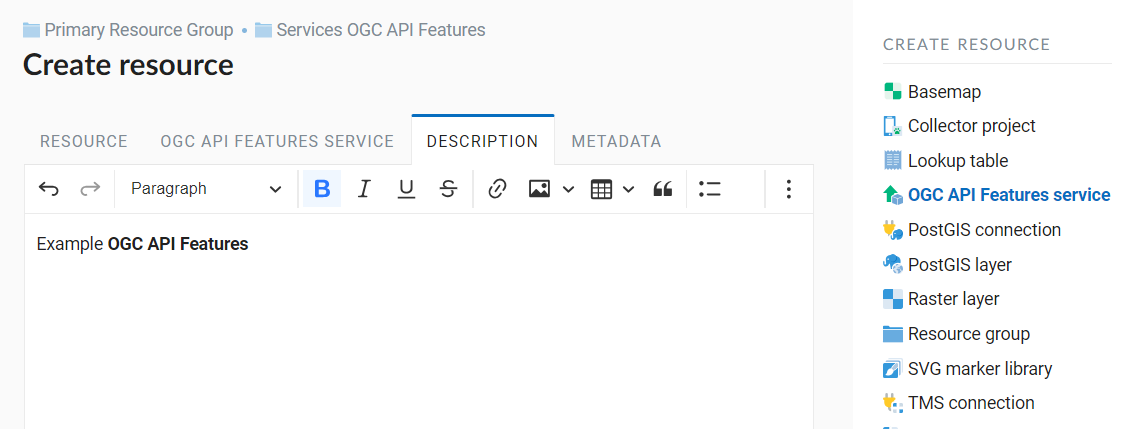
Pic. 5.91. OGC API Features service description
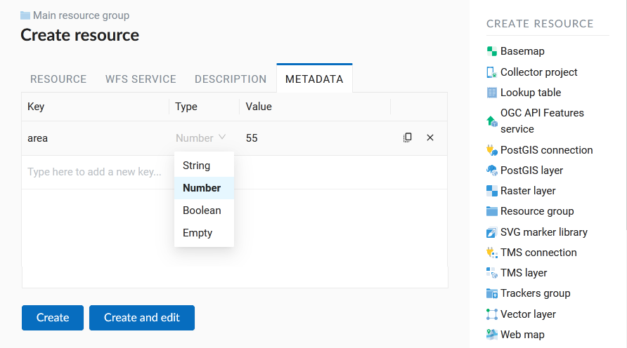
On the “Metadata” tab you can enter information in the “key-value” format.
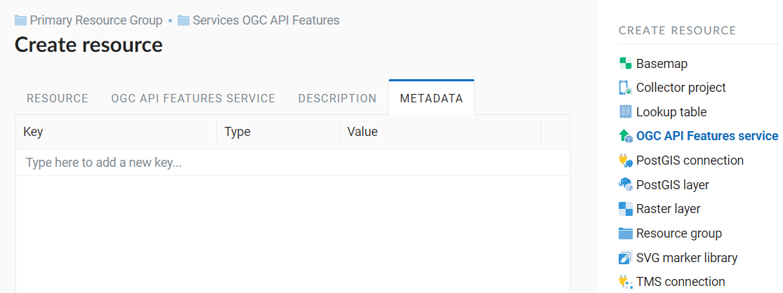
Pic. 5.92. OGC API Features service metadata
Switch to “OGC API Features service” tab, which is presented on Pic. 5.93. and add required layers to a list (see Pic. 5.93.). For each layer you can set a limit for the number of features returned from the vector layer. By default the value is 1000. If this parameter is set to empty, the limit will be disabled and all features will be returned to the client. This may result in high server load and significant timeouts in case of large data volume.
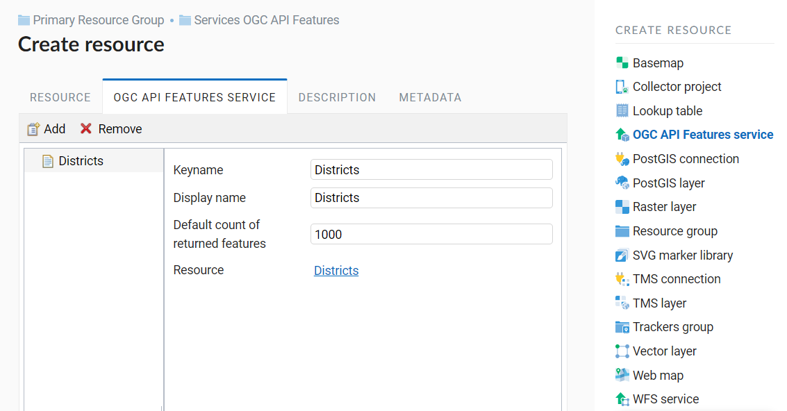
Pic. 5.93. OGC API Features service tab of Create resource dialog
5.5.12.1. Using OGC API Features service
After the resource is created, a URL for the OGC API Features service is available. You can use it in other software, for example QGIS.
You can set access permissions for OGC API Features service if needed. See section Access management.
OGC API Features services can also be accessed with links of the following type (basic auth is supported):
hhttps://yourwebgis.nextgis.com/api/resource/208/ogcf
5.5.13. Creation of a Resource group
Resources can be arranged in groups. For example, you can have special groups for base layers, satellite images and topical data.
Groups help organize the layers in the Control panel and make it easier to manage access permissions.
To create a resource group navigate to the group, where you want to create a new one (root group or another), and in the “Create resource” actions pane click Resource group (see Pic. 5.94.).
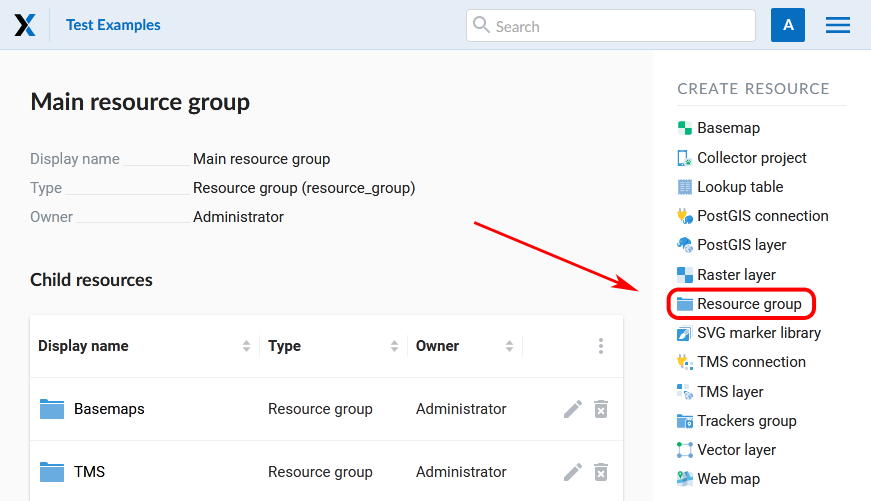
Pic. 5.94. Selection of “Resource group” action
Create resource dialog for resource group is presented on Pic. 5.95..

Pic. 5.95. Create resource dialog for resource group
In the opened dialog enter the name of the resource that will be displayed in the administrator interface and in the map layer tree, and then click Create.
“Keyname” field is optional.
You can also add resource description and metadata on the corresponding tabs.
5.5.14. Lookup table
To create a lookup table navigate to the group, where you want to create it (root group or another), and in the “Create resource” actions pane click Lookup table (see Pic. 5.96.).
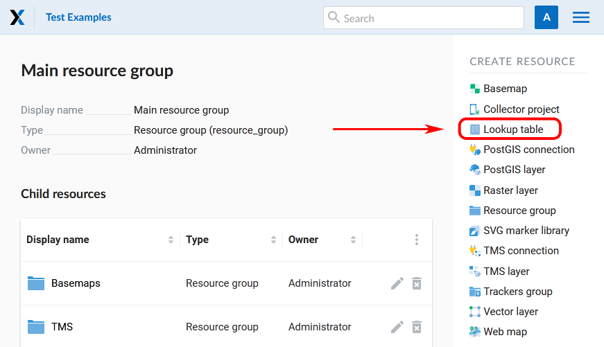
Pic. 5.96. Selection of “Lookup table” action
In the opened dialog enter a display name. “Keyname” field is optional.

Pic. 5.97. Create resource dialog for lookup table
You can also add resource description and metadata on the corresponding tabs.
Switch from “Resource” tab to the “Lookup table” tab, which is presented on Pic. 5.98.. Add data in the “key-value” format. You can also import a pre-made lookup table from a CSV file.
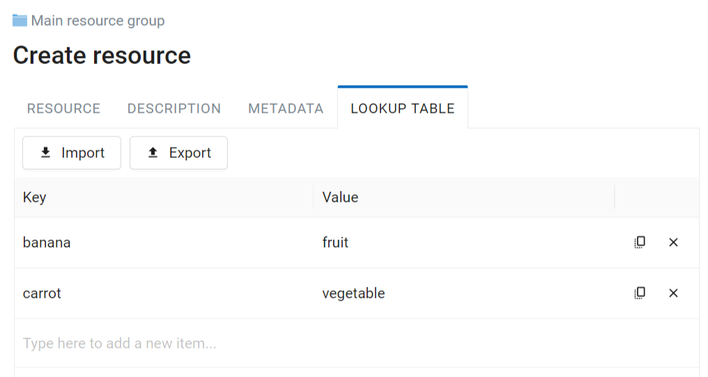
Pic. 5.98. Lookup table tab of Create resource dialog
Then click Save. The window will then look as on Pic. 5.99.

Pic. 5.99. Newly created lookup table
To change anything in a lookup table click Update in the “Action” pane. The resource update dialog will open. Switch to “Lookup table” tab where you can change the table’s contents:
add a new key-value pair
change a current key-value pair
delete a key-value pair
A lookup table can be exported to a CSV file.
You can also connect a lookup table to a field of a vector layer. This way while editing the layer you can choose attribute values from the list. To add a lookup table to the layer, open the Edit dialog for the layer and go to the Attributes tab. In the row of the attribute click on the downward arrow in the Lookup table column to select the table.
5.5.15. SVG Marker Library
In Web GIS you can create SVG marker libraries to be displayed using QGIS styles of vector layers. To create a library, select SVG marker library in the Create Resource actions pane on the right (see Pic. 5.100.).
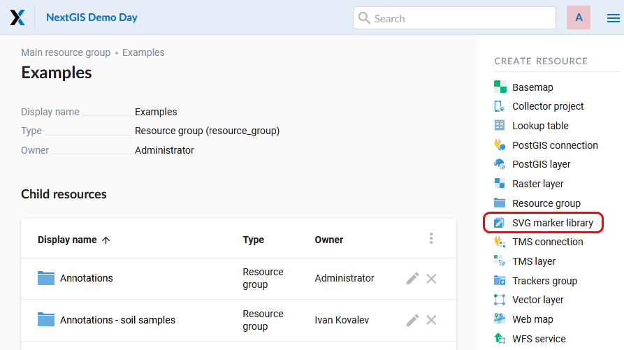
Pic. 5.100. Selecting SVG marker library
In the opened window, enter the name of the resource (see Pic. 5.101.).
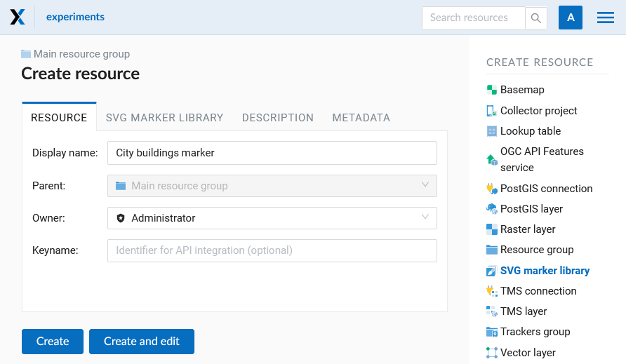
Pic. 5.101. SVG marker library name
Add description and metadata on the corresponding tabs if you need them. In the SVG marker library tab you need to upload SVG markers from your device. You can upload markers as individual files or as a zip-archive. The archive must contain markers only. After all icons have been uploaded to the library, you will see the list of the file names. Click Create to complete the process (see Pic. 5.102.).

Pic. 5.102. Final steps of creating an SVG marker library
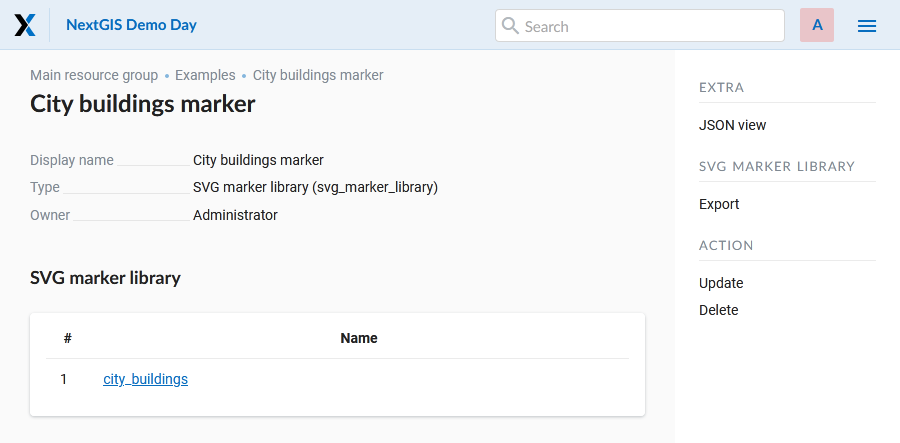
Pic. 5.103. List of SVG markers uploaded to the library
The process of adding marker libraries to vector layer styles is described here.
5.5.16. Typical structure
With NextGIS Web application experience we recommend the following typical structure for organizing resources.
Typical structure
Main resource group
      Web Maps
              Master Web Map
              Test Web Map
      PostGIS connections
              PostGIS on server
      Data layers
              Base data
                      Borders
                      Infrastructure - linear features
                      Accounting area
              Thematic data
                      Results of measurements on accounting area
                      Results of measurements on accounting routes
                      Observation points for rare species
              Relief
                      ASTER DEM
                              DEM
                              Isolines
              Topographic data
                      Openstreetmap
                              Roads
                              Administrative borders
                              Hydrology
                              Railway stations
                              Railway roads
                              Landuse
                      1 : 100000
                              M-37-015
                              M-37-016
                              M-37-017
              Satellite imagery
                      Landsat-8
                      Ikonos